Refrigeration air conditioning system

a refrigeration air conditioning and system technology, applied in the field of refrigeration air conditioning systems, can solve the problems of reducing the cooling performance, increasing the load of the refrigeration air conditioning system, and reducing the cooling efficiency of the refrigeration air conditioning system, and achieve the effect of stable dehumidification performan

Active Publication Date: 2010-01-07
MITSUBISHI ELECTRIC CORP
View PDF5 Cites 20 Cited by
  • Summary
  • Abstract
  • Description
  • Claims
  • Application Information

AI Technical Summary

Benefits of technology

[0014]A refrigeration air conditioning system according to the present invention has a refrigerant circuit filled with a refrigerant and provided with a compressor for compressing the refrigerant, a condenser, a throttling device and an evaporator, and cools a space at a predetermined temperature range of a dry-bulb temperature of 0° C. or less. By providing a moisture adsorption means, which holds an adsorbent having a pore size of 5 μm or less, adsorbs moisture of the air in a cold storage room, and discharges the adsorbed moisture into the atmosphere, the moisture in pores of the moisture adsorption means does not freeze even at a dry-bulb temperature of 0° C. or less and a stable dehumidifying performance is able to be obtained.

Problems solved by technology

Because of this, it has happened that frost is generated in the evaporator, which has reduced the cooling performance.
Accordingly, redundant energy has been consumed for defrosting and caused degradation in cooling efficiency of the refrigeration air conditioning system.
Moreover, after the defrosting operation, the temperature inside the freezing and cold storage warehouses increased, which caused increasing in the load of the refrigeration air conditioning system and increasing in consumed power.

Method used


Image

  • Refrigeration air conditioning system
  • Refrigeration air conditioning system
  • Refrigeration air conditioning system

Examples


embodiment 1

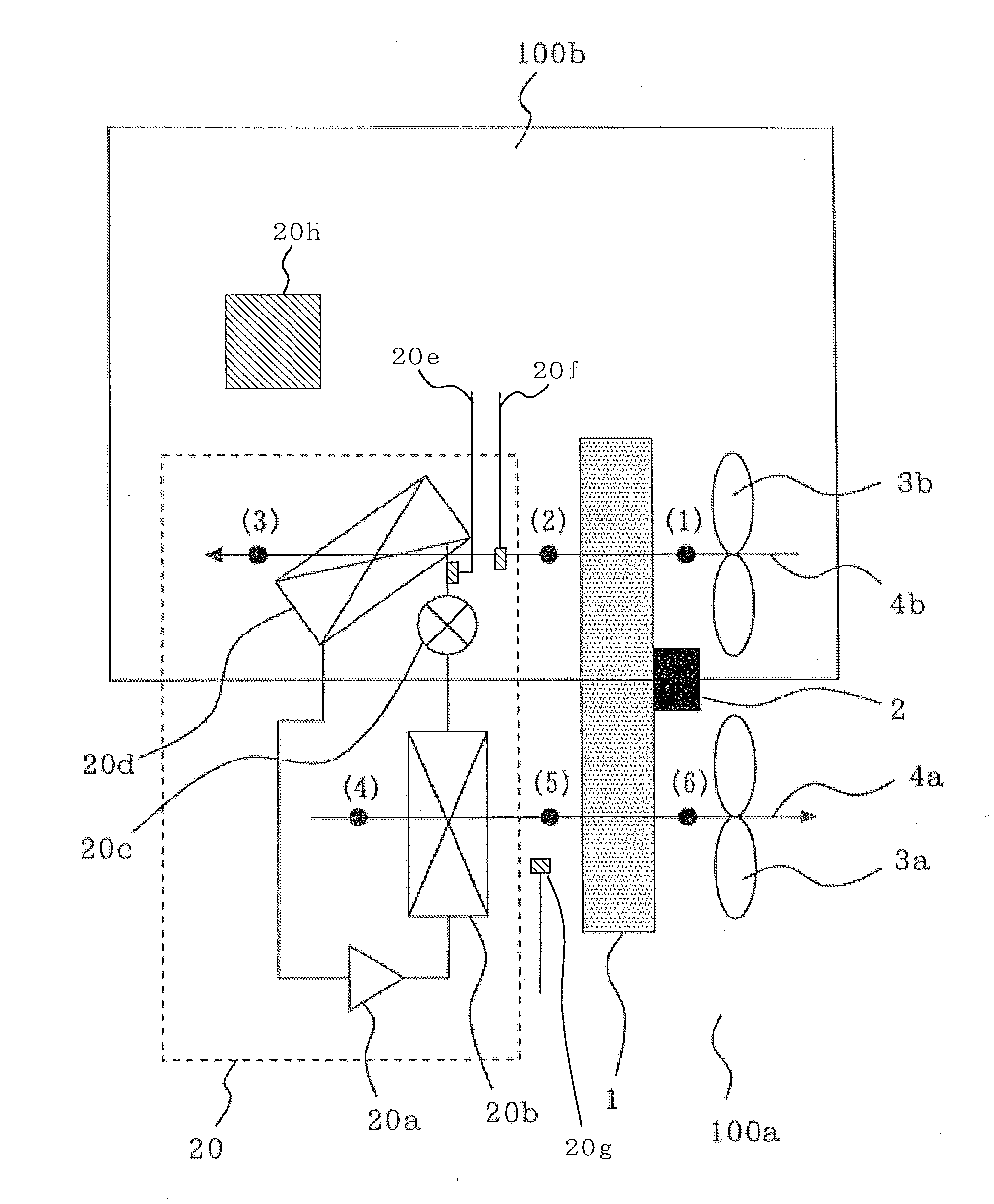
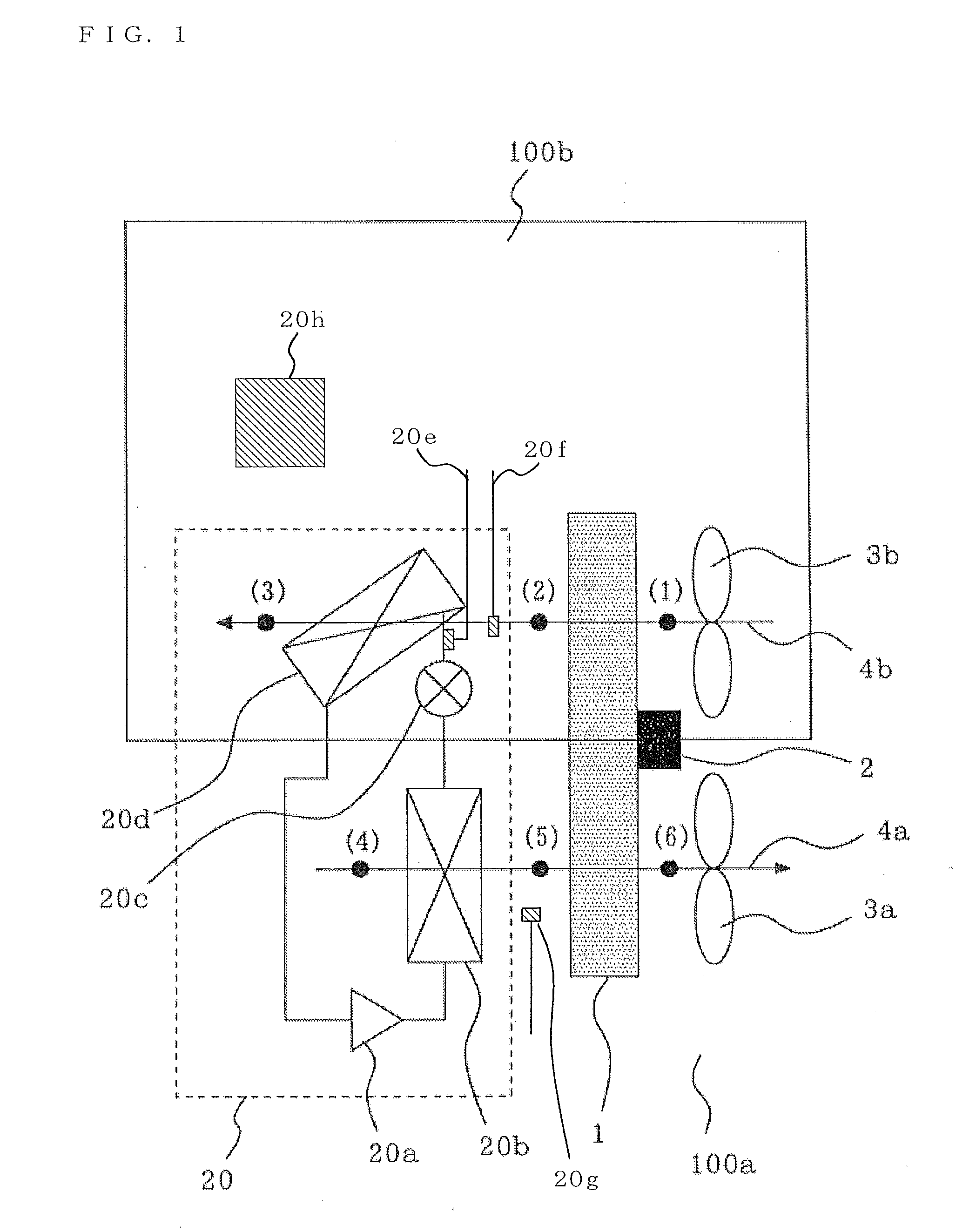
[0030]A constitution of a refrigeration air conditioning system in this Embodiment 1 will be described. FIG. 1 is a schematic view illustrating the constitution of the refrigeration air conditioning system in Embodiment 1 of the present invention. This refrigeration air conditioning system is provided with a desiccant rotor 1 which is a moisture adsorption means, and a refrigerator 20. There are also provided a motor 2 which is a driving means for driving the desiccant rotor 1, a fan 3a which is a first blowing means for supplying first air 4a in an outside-air side space 100a, which is a first air conditioning space, to the desiccant rotor 1, and a fan 3b which is a second blowing means for supplying second air 4b in a cold storage room 100b, which is a second air conditioning space, to the desiccant rotor 1. R404A which is an HFC (Hydro Fluoro Carbon)-based refrigerant is sealed into the refrigerator 20 which is composed of a compressor 20a, a condenser 20b, an expansion valve 20c...


PUM


Abstract

To obtain a refrigeration air conditioning system having a dehumidifying function by means of a moisture adsorption means, allowing the moisture adsorption means to be regenerated by use of discharged condensation heat or other discharged heat of a low temperature range in the refrigeration cycle, and exerting stable cooling performance even at a dry-bulb temperature of 0° C. or less.
A desiccant rotor 1, being a moisture adsorption means, is made to hold an adsorbent having pore sizes of 5 μm or less, more preferably 20 nm or less, and furthermore preferably 1-1.4 nm in a space at a predetermined temperature range of a dry-bulb temperature of 0° C. or less. Forming of frost on an evaporator 20d is prevented by supplying the air dehumidified by the desiccant rotor 1 to the evaporator 20d disposed on the leeward side thereof in a freezing room as the desiccant rotor 1 is rotated, while the adsorbent having adsorbed moisture is made dried and made to recover its adsorbing ability by supplying the air dried by discharged heat from a condenser 20b disposed on the windward side thereof to the desiccant rotor 1 at the outside of the freezing room.

Description

TECHNICAL FIELD[0001]The present invention relates to a refrigeration air conditioning system installed in a cold storage or freezing warehouse and used at a dry-bulb temperature of 0° C. or less.BACKGROUND ART[0002]A conventional refrigeration air conditioning system having a dehumidifying function is composed of a compressor, a condenser, an expansion valve, an evaporator and a defrost heater. In to a refrigeration cycle of the refrigeration air conditioning system, a refrigerant is filled. The refrigerant compressed by the compressor becomes a high-temperature and high-pressure gas refrigerant and is fed to the condenser. The refrigerant flowing into the condenser becomes a liquid by releasing heat into the air. The liquefied refrigerant is depressurized by the expansion valve to become a gas-liquid two-phase state, and becomes a gas in the evaporator by absorbing heat from the surrounding air to flow into the compressor. Especially, since freezing and cold storage warehouses hav...

Claims


Application Information

Patent Timeline
Patent Type & Authority Applications(United States)
IPC IPC(8): F25D17/04F25B1/00F25B15/00
CPCF24F1/022F25D21/04F24F3/1423
Inventor MORIMOTO, HIROYUKISUGIMOTO, TAKESHIMATSUOKA, FUMIOYAMASHITA, TETSUYAYAMASHITA, KOJIMAEGAWA, TAKEYUKI
Owner MITSUBISHI ELECTRIC CORP
Why Eureka
Try Eureka