Work machine

a work machine and work lever technology, applied in the field of work machines, can solve the problems of obstructing the operator, requiring the operator to change, and insufficient fine operation, etc., and achieve the effect of extending the time to chang

Inactive Publication Date: 2010-01-07
CATEPILLAR SARL
View PDF12 Cites 2 Cited by
  • Summary
  • Abstract
  • Description
  • Claims
  • Application Information

AI Technical Summary

Benefits of technology

[0020]According to the present invention, the foot-operated switchover means, which serves to enable the common operating lever to operate the traveling device and the work device, is disposed in the proximity of and operable with a foot of an operator seated at the operating seat. Therefore, switchover can easily be performed and it can also be easily recognized that switchover has taken place. In other words, by operating the foot-operated switchover means with his foot, the operator is able to perform travel operation consciously with the operating lever. By simply removing the foot from the foot-operated switchover means, the operator is able to return the machine to the normal operation mode without having to release his hand from the operating lever.
[0021]According to the present invention, whenever the foot-operated switchover means is stepped on, the foot-operated switchover means activates the traveling alarm, making the operator fully aware that travel operation is being performed with the operating lever. Furthermore, the traveling alarm is sounded prior to travel action taking place by the operating lever, allowing ample time to alert people in the vicinity.
[0022]According to the present invention, should the traveling pedal and the foot-operated switchover means be simultaneously stepped on, the warning alarm is activated to prevent a mix-up that would otherwise be caused by simultaneous commands for travel operation from the traveling pedal and the operating lever.

Problems solved by technology

Operating the traveling pedals with the feet is sufficient for broad travel operation but inadequate to perform fine operation.
Therefore, a structure that includes travel levers disposed in front of the operating seat may cause the travel levers to obstruct the operator from entering or exiting the cab 4, or it compels the operator to change his position or shift his hand when operating a travel lever.
These structures facilitate entering and exiting of the operator but do not solve the problem of switching the hand from the operating lever to perform traveling operation.
In any one of the structures that are offered in the Patent Documents mentioned above and include a switchover device provided separately from the operating levers, the operator has to remove his hand from an operating lever in order to operate the switchover device, which is nearly as inconvenient as switching one's hand from one lever to another.
Even if the switchover device is attached to an operating lever, it is difficult for the operator to ascertain whether switchover has taken place, and the operator has to think about which device the operating lever has engaged for operation at the moment.
As described above, a work machine having travel levers disposed on the floor in front of the operating seat not only makes it difficult for the operator to enter or exist the machine but also compels the operator to change his position or shift his hand when operating a travel lever.
In cases where an operating lever is provided with a switchover device so that switching the switchover device enables travel operation through a work device / swing operating lever, it is difficult for the operator to ascertain whether switchover has taken place.
This may result in a situation such as the operator operating the operating lever by mistake, causing the work device to move when travel operation is intended, or erroneously causing travel operation while intending to operate the work device.

Method used


Image

  • Work machine
  • Work machine
  • Work machine

Examples


Embodiment Construction

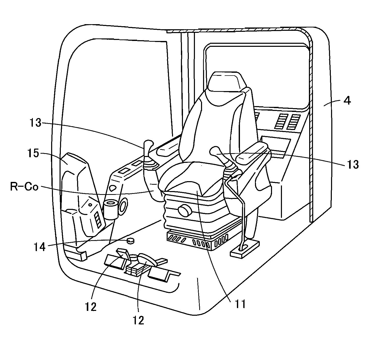
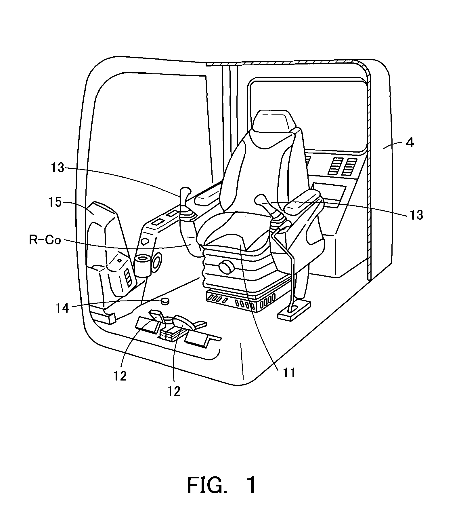
[0013]As described above, a work machine having travel levers disposed on the floor in front of the operating seat not only makes it difficult for the operator to enter or exist the machine but also compels the operator to change his position or shift his hand when operating a travel lever. Even if a switchover device is provided separately from the operating levers, the operator has to remove his hand from an operating lever in order to operate the switchover device.

[0014]In cases where an operating lever is provided with a switchover device so that switching the switchover device enables travel operation through a work device / swing operating lever, it is difficult for the operator to ascertain whether switchover has taken place.

[0015]This may result in a situation such as the operator operating the operating lever by mistake, causing the work device to move when travel operation is intended, or erroneously causing travel operation while intending to operate the work device.

[0016]I...


PUM


Abstract

In a work machine equipped with a switchover means enabling selective operation of traveling devices and a work device by means of common operating levers, switchover can easily be performed and also easily recognized. In a work machine having traveling devices and a work device, operating levers that are capable of operating the traveling devices and the work device are respectively disposed at the sides of an operating seat. A foot switch connected to a controller is disposed in the proximity of and operable with a foot of an operator seated at the operating seat. While the foot switch is being operated with the foot, the traveling devices are operated by the operating levers through the controller. While the foot switch is not being operated, the work device is operated by means of the operating levers through the controller.

Description

CROSS REFERENCE TO RELATED APPLICATIONS[0001]This is a U.S. national phase application under 35 U.S.C. § 371 of International Patent Application No. PCT / JP2006 / 318580, filed Sep. 20, 2006 and claims the benefit of Japanese Application No. 2005-349063, filed Dec. 2, 2005, both of them are incorporated by reference herein. The International Application was published in Japanese on Jun. 7, 2007 as WO 2007 / 063634 under PCT Article 21(2).TECHNICAL FIELD[0002]The present invention relates to a work machine provided with a traveling devices and a work device.BACKGROUND[0003]As shown in FIG. 5, a hydraulic shovel 1 is a work machine provided with a lower structure, an upper swing body 3, a cab 4, and a work device 5. The lower structure has right and left traveling devices 2 adapted to be respectively driven by right and left travel motors 2m. The upper swing body 3 is adapted to be rotated on the lower structure by a swing motor 3m. The cab 4 and the work device 5 are mounted on the upper ...

Claims


Application Information

Patent Timeline
Patent Type & Authority Applications(United States)
IPC IPC(8): G05G1/30
CPCE02F9/2004E02F9/2025Y10T74/20012Y10T74/20528Y10T74/2054
Inventor AKAHANE, EIJITOYOURA, NOBUMIKOJIMA, SHIGERUTAKANO, MASSAYUKI
Owner CATEPILLAR SARL
Why Eureka
Try Eureka