Cam lock for cantilever mounting device

a technology of mounting device and cam lock, which is applied in the direction of washstands, scaffold accessories, lightening support devices, etc., can solve the problems of rotating the adjustment dial, the tension pin the third cam cannot be rotated about the axis so as to increase or decrease the tension of the third joint, increase and reduce the tension of the first joint

Inactive Publication Date: 2010-01-07
ERGOTRON
View PDF24 Cites 10 Cited by
  • Summary
  • Abstract
  • Description
  • Claims
  • Application Information

AI Technical Summary

Benefits of technology

[0010]Furthermore, the third cam allows rotation of the third shaft when the third lever is set to the adjustment position, and the third cam does not allow rotation of the third shaft when the third lever is set to the locked position. The rotation of the third shaft increases or decreases a tension of the third joint. The third cam includes a third base, a third pivot pin, a top pivot, and a bottom pivot. The third pivot pin is inserted into the third lever and the third shaft to secure the third lever, the third base, and the top pivot pin to a first end of the third shaft. The bottom pivot is connected to a second end of the third shaft. A tilt link is connected to the top pivot and the bottom pivot. The tilt link connects the third cam to the front member. The tilt link provides rotation about an axis perpendicular to the axis of the third joint.
[0011]A method for adjusting the position of a cantilever mounting device includes applying force to a first lever of a first cam for reducing a tension of a first joint and for setting the first lever to a first adjustment position. A first arm is rotated relative to a back member about the first joint when the first lever is in the first adjustment position. Force is applied to the first lever for increasing the tension of the first joint and for setting the first lever to a first locked position such that the first arm is locked in place relative to the back member.
[0012]Furthermore, an adjustment dial of the first cam is rotated to reduce the tension of the first joint when the first lever is set to the first adjustment position. Force is applied to a second lever of a second cam for reducing a tension of a second joint and for setting the second lever to a second adjustment position. A second arm is rotated relative to the first arm about the second joint when the second lever is in the second adjustment position. Force is applied to the second lever for increasing the tension of the second joint when the second lever is in the second adjustment position. Force is applied to the second lever for increasing the tension of the second joint and for setting the second lever to a second locked position such that the second arm is locked in place relative to the first arm. Force is applied to a third lever of a third cam for reducing a tension of a third joint and for setting the third lever to a third adjustment position. A front member is rotated relative to the second arm about the third joint when the third lever is in the adjustment position. Force is applied to the third lever for increasing the tension of the third joint and for setting the third lever to a third locked position such that the front member is locked in place relative to the second arm. The front member is tilted about an axis perpendicular to the third joint.

Problems solved by technology

The first cam allows rotation of the adjustment dial when the first lever is set to the first adjustment position, and the first cam does not allow rotation of the adjustment dial when the first lever is set to the first locked position.
The second cam allows rotation of the tension pin when the second lever is set to the second adjustment position, and the second cam does not allow rotation of the tension pin when the second lever is set to the second locked position.
The third cam does not allow rotation about an axis of the third joint when the third lever is set to the locked position.

Method used


Image

  • Cam lock for cantilever mounting device
  • Cam lock for cantilever mounting device
  • Cam lock for cantilever mounting device

Examples


Embodiment Construction

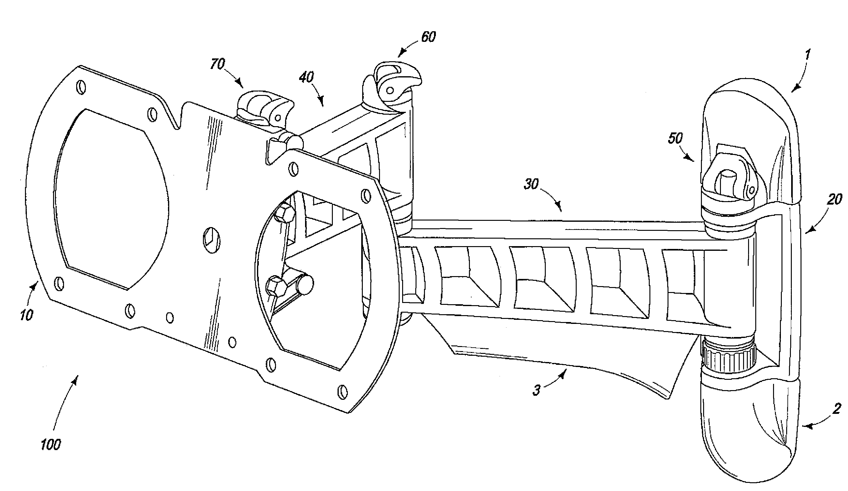
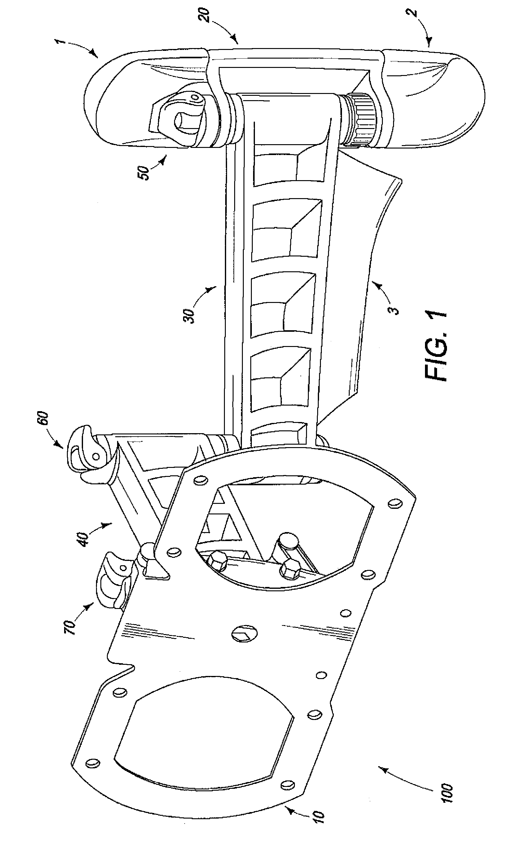
[0032]One embodiment of a mounting device 100 is illustrated in FIG. 1 and can be used to display a flat panel television against a wall in a home entertainment center. Mounting device 100 is a cantilever style device that includes a front member such as a front plate 10 for mounting a flat-panel display, electronic device, or any other object suitable for mounting. Opposite front plate 10 is provided a back member or back plate 20 for attaching mounting device 100 to a support structure able to bear the weight of mounting device 100 and mounted object. The support structure is preferably a wall but can be any load-bearing structure. Plastic caps 1 and 2 are provided to cover the top and bottom portions of back plate 20. Caps 1 and 2 conceal screws (not shown) provided to attach back plate 20 to a wall, and will be discussed in more detail with respect to FIG. 2B. A lower arm cap 3 is optionally provided below lower arm 30 to conceal back plate 20 from view.

[0033]Mounting device 100...


PUM


Abstract

A cantilever mounting device includes a front member on which an object is mounted and a back member for attachment to a load-bearing surface. A first arm is connected to the back member to form a rotatable first joint. A second arm is connected to the first arm to form a rotatable second joint. The front member is connected to the second arm to form a rotatable third joint. The first joint includes a first cam including a first lever and a first shaft for connecting the back member to the first arm. The first cam allows rotation about an axis of the first joint when the first lever is set to a first adjustment position. The first cam does not allow rotation about the axis of the first joint when the first lever is set to a first locked position.

Description

BACKGROUND OF THE INVENTION [0001]1. Field of the Invention[0002]This invention relates to tension adjustment for a cantilever mounting device.[0003]2. Description of Related Art[0004]Flat panel displays have become increasingly popular in home entertainment systems. Generally, flat panel displays have a limited viewing angle, thus making the positioning of the display important to a viewer. Flat panel displays are typically placed on stands or are mounted to a wall by flat panel mounting devices. These mounting devices include articulating joints and are conventionally preset with an optimal joint / tilt tension during manufacturing to the joints of the articulating components and tilt mechanisms. The preset tension allows the flat panel mounting device to steadily and predictably hold a display in place. However, periodic adjustment is required to readjust the tension of the joints and tilt mechanism to maintain a desired viewing position. Furthermore, if a user decides to change a ...

Claims


Application Information

Patent Timeline
Patent Type & Authority Applications(United States)
IPC IPC(8): A47B96/07
CPCF16M11/04F16M11/10F16M11/2014F16M2200/061F16M13/02F16M2200/022F16M11/2092
Inventor STENHOUSE, BRETTTOWNSEND, MICHAELZUCKERMAN, RAYDONACHY, JOHN C.
Owner ERGOTRON
Why Eureka
Try Eureka