Inductive position sensor

a position sensor and inductive technology, applied in the direction of measuring devices, instruments, coils, etc., can solve the problems of optical sensor obscuration, failure with little or no warning, optical system requires very fine optical gratings for high resolution measuremen

Inactive Publication Date: 2010-01-07
HOWARD MARK ANTHONY +1
View PDF10 Cites 47 Cited by
  • Summary
  • Abstract
  • Description
  • Claims
  • Application Information

AI Technical Summary

Benefits of technology

[0039]Preferably the detector measures temperature by measuring the resistance of at least one of the antenna's windings.

Problems solved by technology

As with most optical systems, any ingress of foreign matter such as dirt or grease can cause obscuration of the optical sensor.
This can cause failure with little or no warning.
Further, such optical systems require very fine optical gratings for high resolution measurement.
These fine gratings exacerbate the susceptibility to foreign matter, as well as being difficult and expensive to manufacture.
These are also available from companies such as Baumer Electric Ltd., but typically do not provide high measurement resolution compared to optical systems.
Further problems include susceptibility to stray electromagnetic fields and batch to batch variability of the magnets caused by differences in material composition.
Without comprehensive shielding the device would be highly susceptible to electromagnetic disturbances.
High input energy produces high electromagnetic emissions and the minimal stand-off distance limits the scope of application.
It is not generally suitable for applications such as motor encoders which require accurate and rapid position measurement at speeds of >10000 rpm.
These via holes distort the antenna's electromagnetic field and the high number required for multi-pitch designs, especially in small encoders, is problematic in designing high resolution measurement systems with good linearity (typically <1%).
These problems are particularly acute given the increasing use of small DC brushless motors in products such as cameras, consumer electronics and computer controlled devices where the permissible space envelope for a motor encoder can be <30 mm diameter and often <20 mm.

Method used


Image

  • Inductive position sensor
  • Inductive position sensor
  • Inductive position sensor

Examples


Embodiment Construction

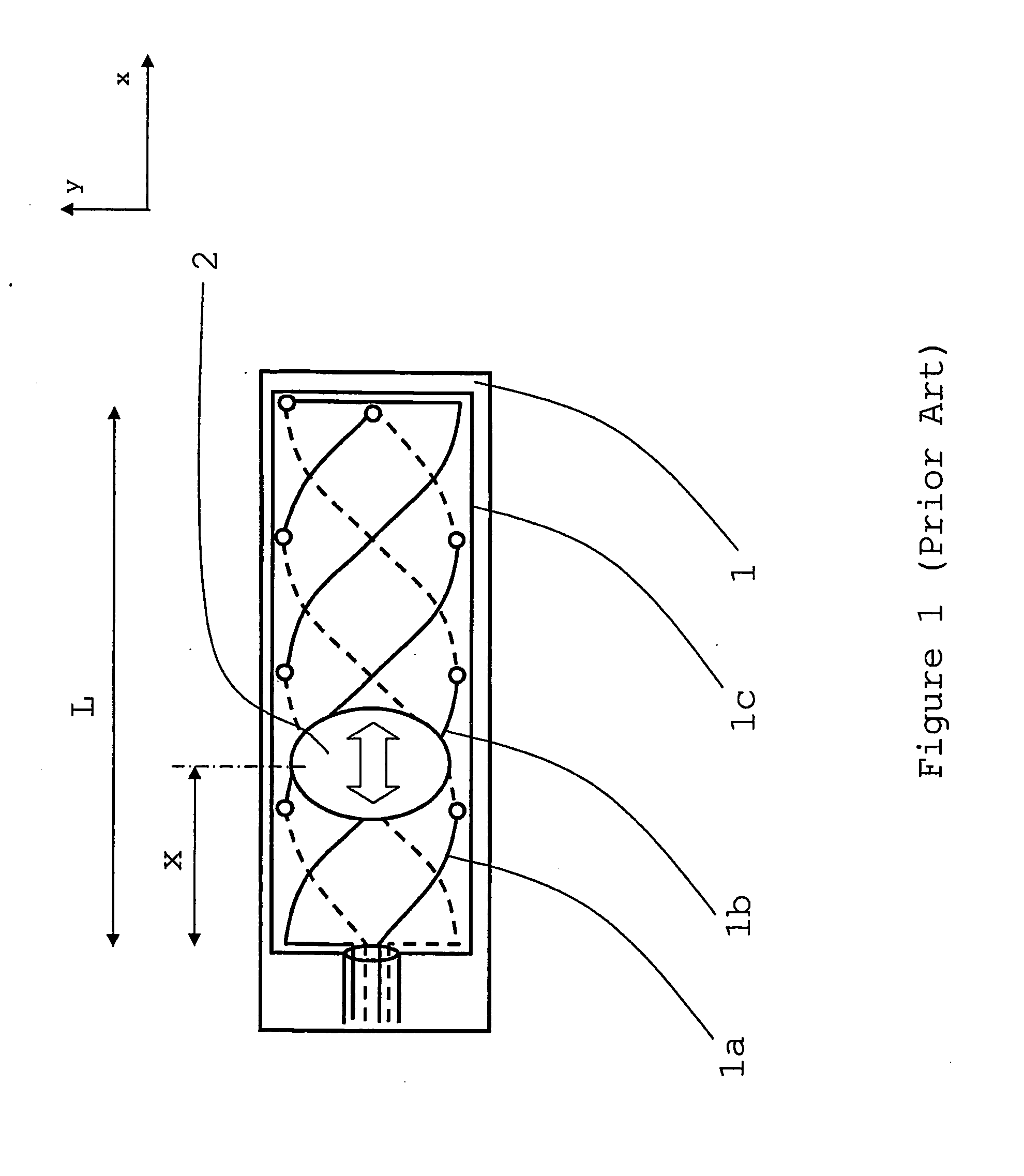
[0056]FIG. 1 shows a simplified, schematic, plan view of a known form of position encoder. An antenna [1] contains a sinusoidal receive winding [1a] and a cosinusoidal receive winding [1b], surrounded by a transmit winding [1c] co-operating with an electrical intermediate device [2]. The two receive windings [1a &1b] are displaced by ¼ of the winding pitch along the measurement (x) axis. The two receive windings [1a &1b] are arranged in series of loops along the measurement axis such that voltages induced in adjacent loops oppose each other. The loops in the receive windings [1a &1b] are formed using via or plated through holes positioned on either side of the measurement axis. It should be noted that in this much simplified example only 8 vias are shown for reasons of clarity. However, in practice, each of the receive windings [1a &1b] is likely to use multiple turns in each loop and consequently many more than 8 vias will be required. >100 vias may be required if a multi-pitch arr...


PUM


Abstract

A detector to measure the displacement of relatively moveable bodies along an axis comprising: a resonant electrical intermediate device further comprising an inductor, whose width varies along the displacement axis, and a capacitor in electrical series which co-operates with an antenna comprising transmit and receive windings whose mutual inductance varies according to the position of the electrical intermediate device relative to the antenna.

Description

FIELD OF THE INVENTION [0001]This invention relates to an inductive displacement detector, operable to measure the displacement of relatively moveable bodies and which has particular, but not exclusive, relevance to motor encoders.REVIEW OF THE ART KNOWN TO THE APPLICANT [0002]Various forms of detector have been used to measure the position of two relatively moveable bodies. They are variously referred to as detectors, sensors, transducers, encoders, measurement devices or systems.[0003]A common form of encoder is the optical encoder. This type of encoder typically uses an optical grating which moves relative to an optical transmitter and receiver. Such devices are widely available from companies such as Baumer Electric Ltd., Shrivenham Hundred Business Park, Watchfield, Wiltshire, England. As with most optical systems, any ingress of foreign matter such as dirt or grease can cause obscuration of the optical sensor. This can cause failure with little or no warning. Further, such opt...

Claims


Application Information

Patent Timeline
Patent Type & Authority Applications(United States)
IPC IPC(8): G01B7/14
CPCG01B7/003G01B7/14G01B7/30
Inventor HOWARD, MARK ANTHONYKREIT, DARRAN
Owner HOWARD MARK ANTHONY
Why Eureka
Try Eureka