Anti-shake device for optical instrument

an optical instrument and anti-shake technology, applied in the field of anti-shake devices, can solve the problems of increasing manufacturing costs and assembly time of anti-shake devices, aberration of imaging, etc., and achieve the effects of preventing aberration of imaging, reducing manufacturing costs, and not high precision of anti-shake devices

Inactive Publication Date: 2010-01-07
ASIA OPTICAL INT LTD
View PDF10 Cites 6 Cited by
  • Summary
  • Abstract
  • Description
  • Claims
  • Application Information

AI Technical Summary

Benefits of technology

[0012]The first and second clamping arms position the image-capturing unit using a clamping manner, such that a positioning effect can be achieved and inclination of the image-capturing unit can be prevented when the precision of members of the anti-shake device is not high. In addition to reducing manufacturing costs and preventing aberration of imaging, the anti-shake device enables the first and second clamping arms to separate from the image-capturing unit with a small driving force.

Problems solved by technology

To suppress the positioning deviation, the manufacturing and assembly precision of the positioning member 13 must be enhanced, thus increasing manufacturing costs and assembly time of the anti-shake device 1.
Moreover, because the positioning member 13 abuts only one side of the image-capturing unit A, the other side of the image-capturing unit A is easily raised, causing inclination of the image-capturing unit A. Thus, an imaging surface of the image-capturing unit A cannot be symmetrical to the optical axis, causing aberration of imaging.

Method used


Image

  • Anti-shake device for optical instrument
  • Anti-shake device for optical instrument
  • Anti-shake device for optical instrument

Examples


Embodiment Construction

[0020]The following description is of the best-contemplated mode of carrying out the invention. This description is made for the purpose of illustrating the general principles of the invention and should not be taken in a limiting sense. The scope of the invention is best determined by reference to the appended claims.

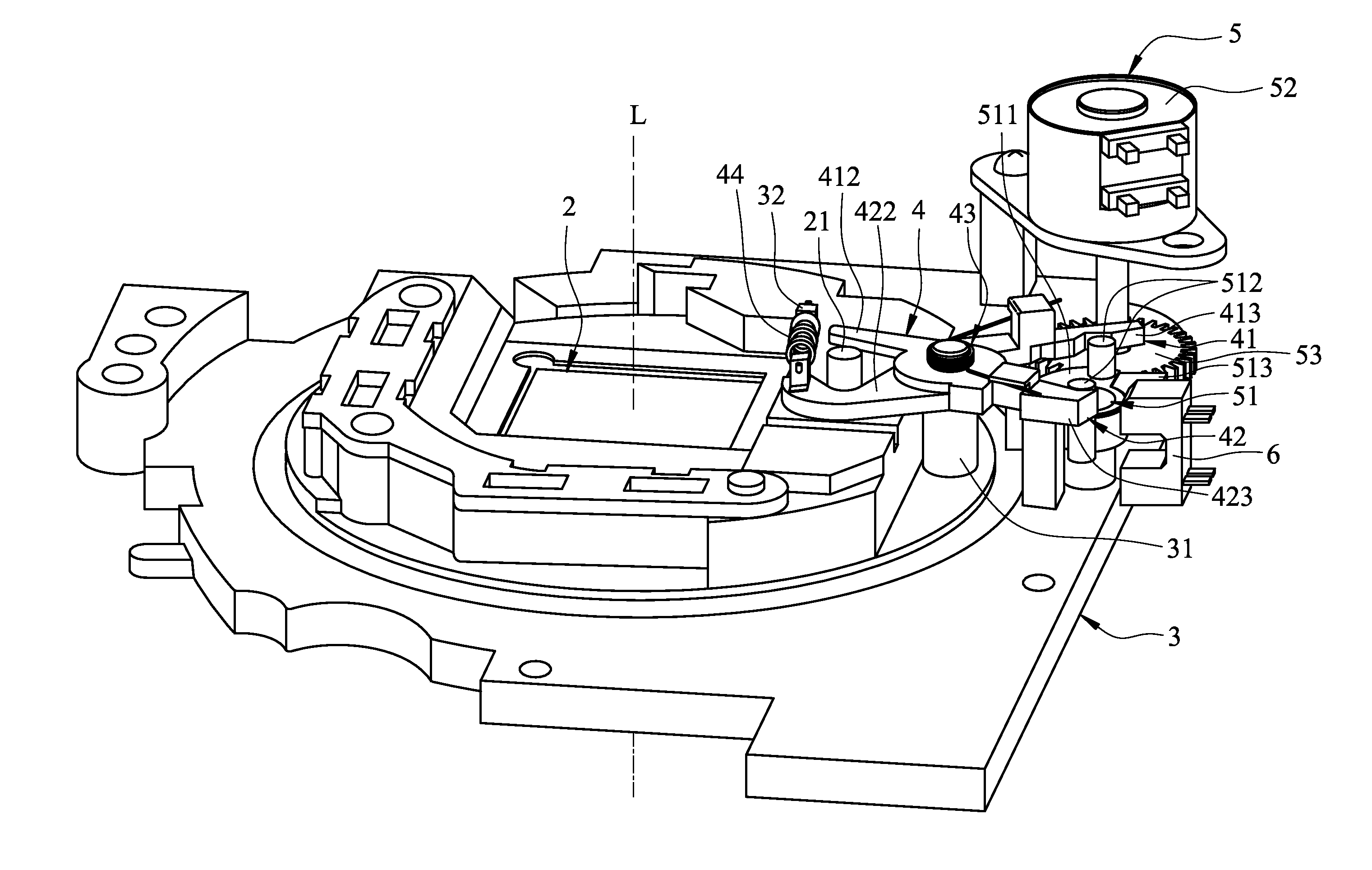
[0021]Referring to FIG. 3 and FIG. 5, an anti-shake device for positioning an image-capturing unit 2 in an optical instrument is disclosed. The image-capturing unit 2 comprises an optical axis L and a positioning pillar 21 extending along the optical axis L. The anti-shake device comprises a base 3, a clamp unit 4, a drive unit 5, and a sensor 6.

[0022]The base 3 comprises a shaft pillar 31 and a protruding pillar 32.

[0023]The clamp unit 4 comprises a first clamping arm 41, a second clamping arm 42, a resilient member 43, and a repositioning member 44. The first clamping arm 41 and second clamping arm 42 pivot to the shaft pillar 31 of the base 3. The resilient member 4...


PUM


Abstract

An anti-shake device for positioning an image-capturing unit in an optical instrument. A base includes a shaft pillar. A clamp unit includes a first clamping arm and a second clamping arm. The first and second clamping arms pivot to the shaft pillar of the base and detachably clamp the image-capturing unit. A drive unit is connected to the base and includes a driven member driving the first and second clamping arms of the clamp unit to rotate and shifting between a first mode and a second mode. The first and second clamping arms are separated from each other and the image-capturing unit when the driven member is in the first mode. The first and second clamping arms close and clamp the image-capturing unit when the driven member is in the second mode.

Description

CROSS REFERENCE TO RELATED APPLICATIONS[0001]This Application claims priority of Taiwan Patent Application No. 97124866, filed on Jul. 2, 2008, the entirety of which is incorporated by reference herein.BACKGROUND OF THE INVENTION[0002]1. Field of the Invention[0003]The invention relates to an anti-shake device, and more particularly to an anti-shake device for an optical instrument that provides positioning functions with a clamping manner.[0004]2. Description of the Related Art[0005]In a conventional anti-shake digital camera, a driving circuit drives a floating image-capturing unit to move at a high speed in two directions on a plane perpendicular to an optical axis, suppressing a blurred image or preventing a blurred image from occurring due to shakes during image capture, and further providing anti-shake functions.[0006]Referring to FIG. 1 and FIG. 2, a conventional anti-shake device 1 is employed to quickly position an image-capturing unit A which has been moved at a high speed...

Claims


Application Information

Patent Timeline
Patent Type & Authority Applications(United States)
IPC IPC(8): H04N5/228
CPCH04N5/2253H04N5/23287H04N5/23248H04N23/54H04N23/68H04N23/687
Inventor HUANG, DUN-KUILAI, BING-REN
Owner ASIA OPTICAL INT LTD
Why Eureka
Try Eureka