

Macro lens
- Summary
- Abstract
- Description
- Claims
- Application Information
AI Technical Summary
Benefits of technology
Problems solved by technology
Method used
Image

Examples
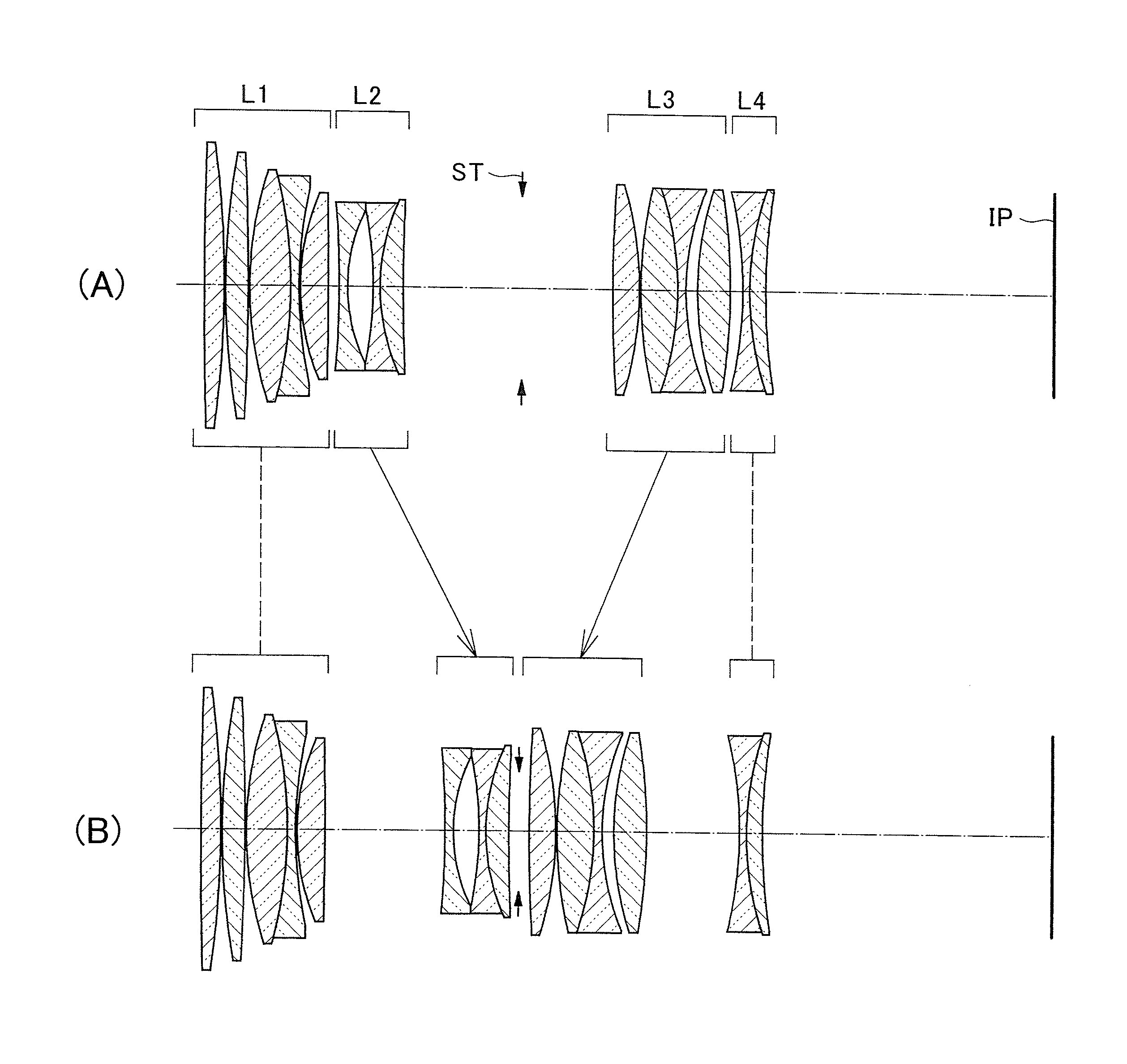
embodiment 1
[0046]
f = 61.5000 FNo. = 2.06 2ω = 26.6°No.RDNdνd1607.14122.85881.8061033.32−150.87740.20003106.56133.26641.8061040.94−386.77960.2000552.17045.90431.4970081.66−63.68771.20001.7552027.5763.68770.2000833.34404.03011.4970081.69−900.5149D(9) 10−141.82331.20001.8040046.61124.13273.720612−53.87621.00001.5168064.21329.08653.34091.8466623.814243.7428D(14)15INFD(15)16229.92303.86201.6968055.517−50.25590.20001862.06425.37441.7725049.619−44.00941.20001.7282528.52035.97341.69002145.21884.77741.6968055.522−88.5480D(22)23−58.50661.00001.5407247.22443.55282.32101.8466623.82588.0000Varied Distance Between Surfaces∞Up to 5:1 Mag.Up to 1:1 Mag.f61.500065.188552.3578FNo.2.062.464.10D(9)1.58484.694817.4252D(14)17.287314.17741.4470D(15)13.217910.59051.5000D(22)1.82054.447913.5384Values of Terms in Conditional FormulaeFormula (1)f1 / f = 0.65Formula (2)| Nd2 − Nd1 | = 0.276Formula (3)| νd1 −νd2 | = 54.1Formula (4)f2 / f = −0.40
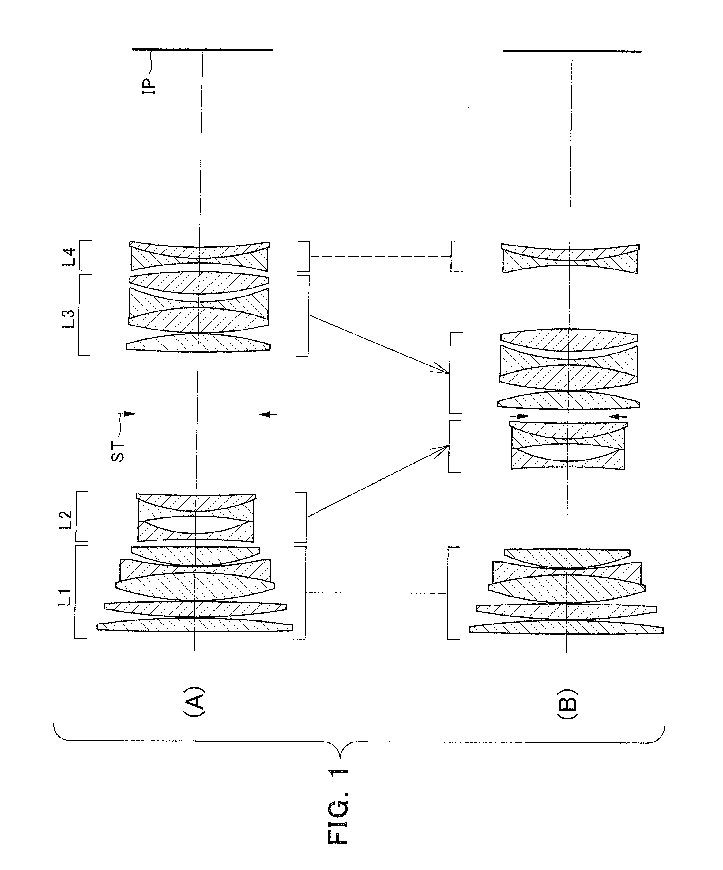
embodiment 2
[0047]
f = 61.5000 FNo. = 2.06 2ω = 26.5°No.RDNdνd1440.66883.69411.7130053.82−139.11390.2000380.42223.40571.6968055.54559.95780.2000541.07524.66641.6968055.56259.63530.460971284.05401.20001.7847225.7830.22384.38601.7725049.69175.0786D(9) 10104.26041.20001.7725049.61124.72763.748812−57.98051.00001.6127258.81322.00410.93391426.34584.12931.8466623.815−133.28160.985416−42.62661.00001.8061033.317508.8701D(17)18INFD(18)192776.42463.50721.7995242.220−48.93930.20002180.87591.20001.7847225.72227.63465.58701.4970081.623−111.92080.20002460.70025.12411.4970081.625−43.4654D(25)26−48.55191.00001.6727032.12723.31874.67921.8466623.82889.1954Varied Distance Between Surfaces∞Up to 1:1 Mag.f61.500055.2183FNo.2.064.10D(9)1.000019.4981D(17)19.85281.3546D(18)7.65001.5000D(25)1.00377.1537Values of Terms in Conditional FormulaeFormula (1)f1 / f = 0.65Formula (2)| Nd2 − Nd1 | = 0.012Formula (3)| νd1 −νd2 | = 23.9Formula (4)f2 / f = −0.35
PUM
 Abstract
Description
Claims
Application Information