
Zoom lens and image pickup apparatus

Inactive Publication Date: 2021-05-13
CANON KK
View PDF0 Cites 0 Cited by
  • Summary
  • Abstract
  • Description
  • Claims
  • Application Information

AI Technical Summary

Benefits of technology

The patent describes a zoom lens that has a high zoom ratio, large aperture ratio, small size, and weight. Additionally, it has high optical performance.

Problems solved by technology

Further, in order to obtain the zoom lens having the high zoom ratio, it is difficult to sufficiently correct axial chromatic aberration and chromatic aberration of magnification on the telephoto side.

Method used


Image

  • Zoom lens and image pickup apparatus
  • Zoom lens and image pickup apparatus
  • Zoom lens and image pickup apparatus

Examples


embodiment 1

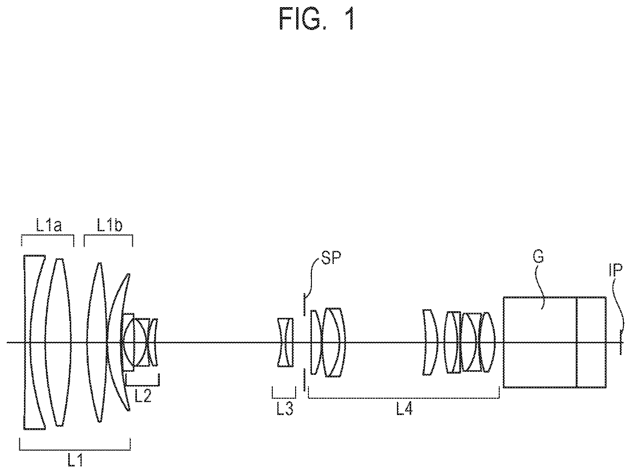
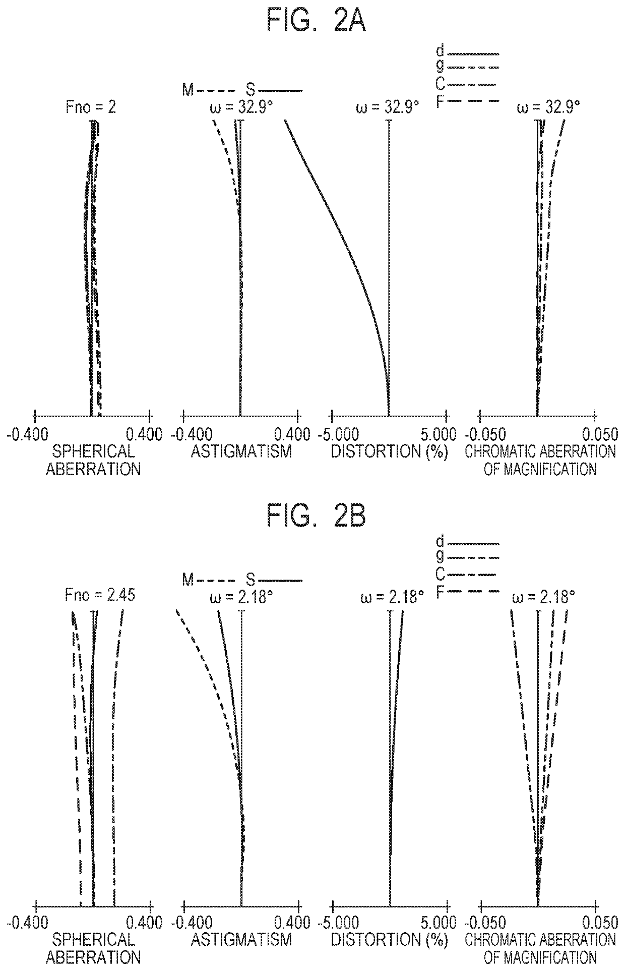
[0050]FIG. 1 is a lens cross-sectional view of Embodiment 1 at a wide angle end. Embodiment 1 relates to a zoom lens having a zoom ratio of 17× and an aperture ratio of about 2. In the lens cross-sectional view, the left side is the object side (front side), and the right side is the image side (back side). When “i” represents the order of a lens unit from the object side, Li represents the i-th lens unit. An optical block, such as a prism or an optical filter, is denoted by G. An aperture stop is denoted by SP. An image plane is denoted by IP. When the zoom lens is used as an image pickup optical system of a digital camera, a video camera, or a monitoring camera, the image plane IP corresponds to an image pickup surface of an image pickup element (photoelectric conversion element), such as a CCD sensor or a CMOS sensor. The same applies to Embodiments to be described later.

[0051]The zoom lens according to Embodiment 1 consists of, in order from the object side to the image side, th...

embodiment 2

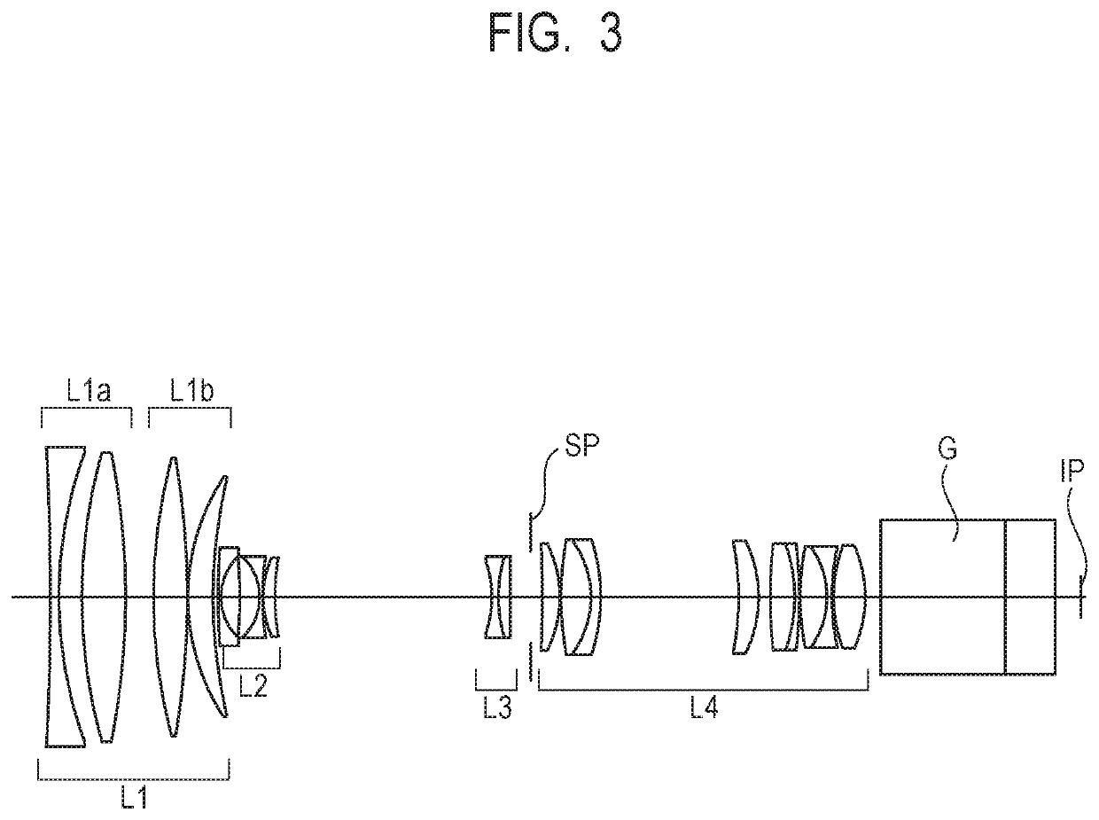
[0054]FIG. 3 is a lens cross-sectional view of Embodiment 2 at a wide angle end. Embodiment 2 relates to a zoom lens having a zoom ratio of 17× and an aperture ratio of about 2.

[0055]A schematic configuration and movements in zooming and focusing of lens units of the zoom lens according to Embodiment 2 are similar to those in Embodiment 1, and hence description thereof is omitted.

[0056]FIG. 4A and FIG. 4B show aberration diagrams of Embodiment 2 when focus is at infinity at the wide angle end and the telephoto end, respectively.

embodiment 3

[0057]FIG. 5 is a lens cross-sectional view of Embodiment 3 at a wide angle end. Embodiment 3 relates to a zoom lens having a zoom ratio of 17× and an aperture ratio of about 2.

[0058]A schematic configuration and movements in zooming and focusing of lens units of the zoom lens according to Embodiment 3 are similar to those in Embodiment 1, and hence description thereof is omitted.

[0059]FIG. 6A and FIG. 6B show aberration diagrams of Embodiment 3 when focus is at infinity at the wide angle end and the telephoto end, respectively.


PUM


Abstract

Provided is a zoom lens including, in order from an object side: a positive first lens unit configured not to move for zooming; a negative second lens unit configured to move in zooming; a negative third lens unit configured to move in zooming; and a positive lens unit configured not to move for zooming, wherein an interval between each pair of adjacent lens units is changed in zooming, wherein the positive first lens unit consists of, in order from the object side: a first lens sub unit configured not to move for focusing; and a second lens sub unit configured to move toward the object side for focusing from infinity to minimum object distance, the first lens sub unit including a negative lens arranged closest to the object side, and wherein an Abbe number of the negative lens and a partial dispersion ratio of the negative lens are appropriately set.

Description

BACKGROUND OF THE INVENTIONField of the Invention[0001]The present invention relates to a zoom lens and an image pickup apparatus.Description of the Related Art[0002]With increasing functionality of an image pickup apparatus (came using an image pickup element, it is required for a zoom lens used in the image pickup apparatus to have a high zoom ratio, a large aperture ratio, and high optical performance. In particular, a CCD, a CMOS, and other such image pickup devices used in professional-use television cameras or cinema cameras have high resolution that is highly uniform over an entire image pickup range. Therefore, it is required for the zoom lens to have high resolution that is highly uniform from the center to the periphery of an image and small chromatic aberration.[0003]In Japanese Patent Application Laid-Open No. H07-151966, there is disclosed a zoom lens consisting of, in order from an object side to an image side, a first lens unit having a positive refractive power, a se...

Claims


Application Information

Patent Timeline
IPC IPC(8): G02B15/14
CPCG02B15/144109G02B15/145125G02B27/0012G02B27/0025
Inventor LEE, YONGHEE
Owner CANON KK
Learn More