Lubricating Member For Linear Motion Rolling Guide Unit And Slider For Linear Motion Rolling Guide Unit

a technology of linear motion and roller, which is applied in the direction of sliding contact bearings, mechanical devices, engine components, etc., can solve the problems of shortening the effective period of lubricating capability, insufficient lubricant required, and inability to uniformly lubrica

Active Publication Date: 2010-01-07
NIPPON THOMPSON
View PDF4 Cites 14 Cited by
  • Summary
  • Abstract
  • Description
  • Claims
  • Application Information

AI Technical Summary

Benefits of technology

[0043]According to the present invention, when the lubricant is fed from the oiling ports, the lubricant is temporarily stored in the oil reservoir and the

Problems solved by technology

As a result, the side portion 4b located at a higher level lacks lubricant, giving rise to the impossibility of uniform lubrication.
In addition, if lubricant is unevenly distributed as de

Method used


Image

  • Lubricating Member For Linear Motion Rolling Guide Unit And Slider For Linear Motion Rolling Guide Unit
  • Lubricating Member For Linear Motion Rolling Guide Unit And Slider For Linear Motion Rolling Guide Unit
  • Lubricating Member For Linear Motion Rolling Guide Unit And Slider For Linear Motion Rolling Guide Unit

Examples


first embodiment

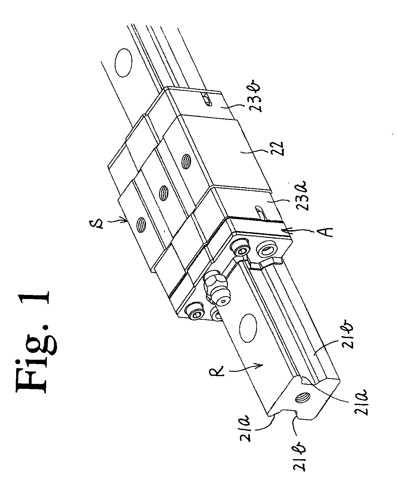
[0057]In a first embodiment illustrated in FIGS. 1 to 3, FIG. 1 is a perspective view illustrating a slider S movably straddling a rail R. The rail R is recessed in its opposing side faces to form recesses extending in the longitudinal direction. The upper and lower surfaces of each of the recesses serve as raceway faces 21a and 21b corresponding to the raceway sections of the present invention.

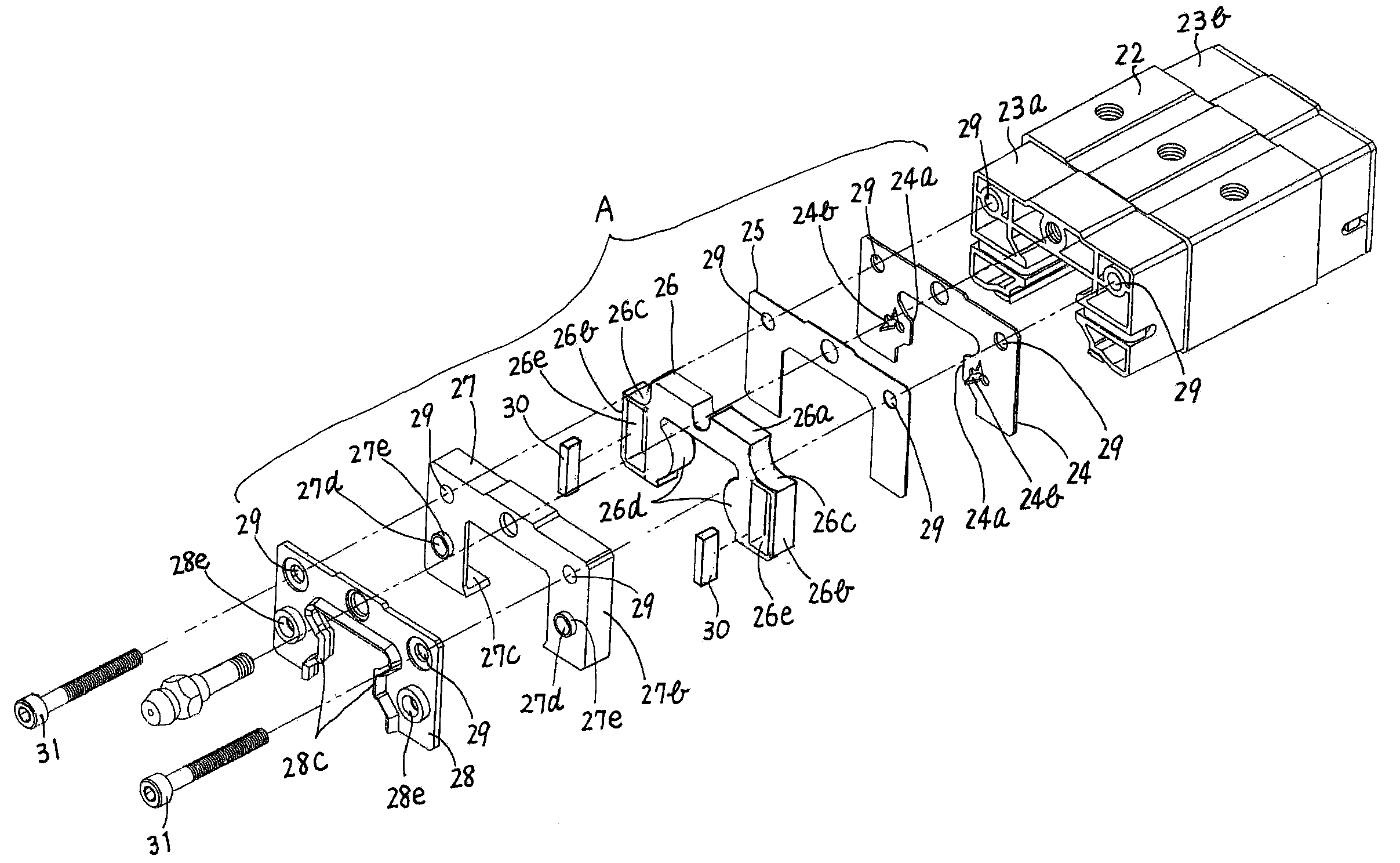
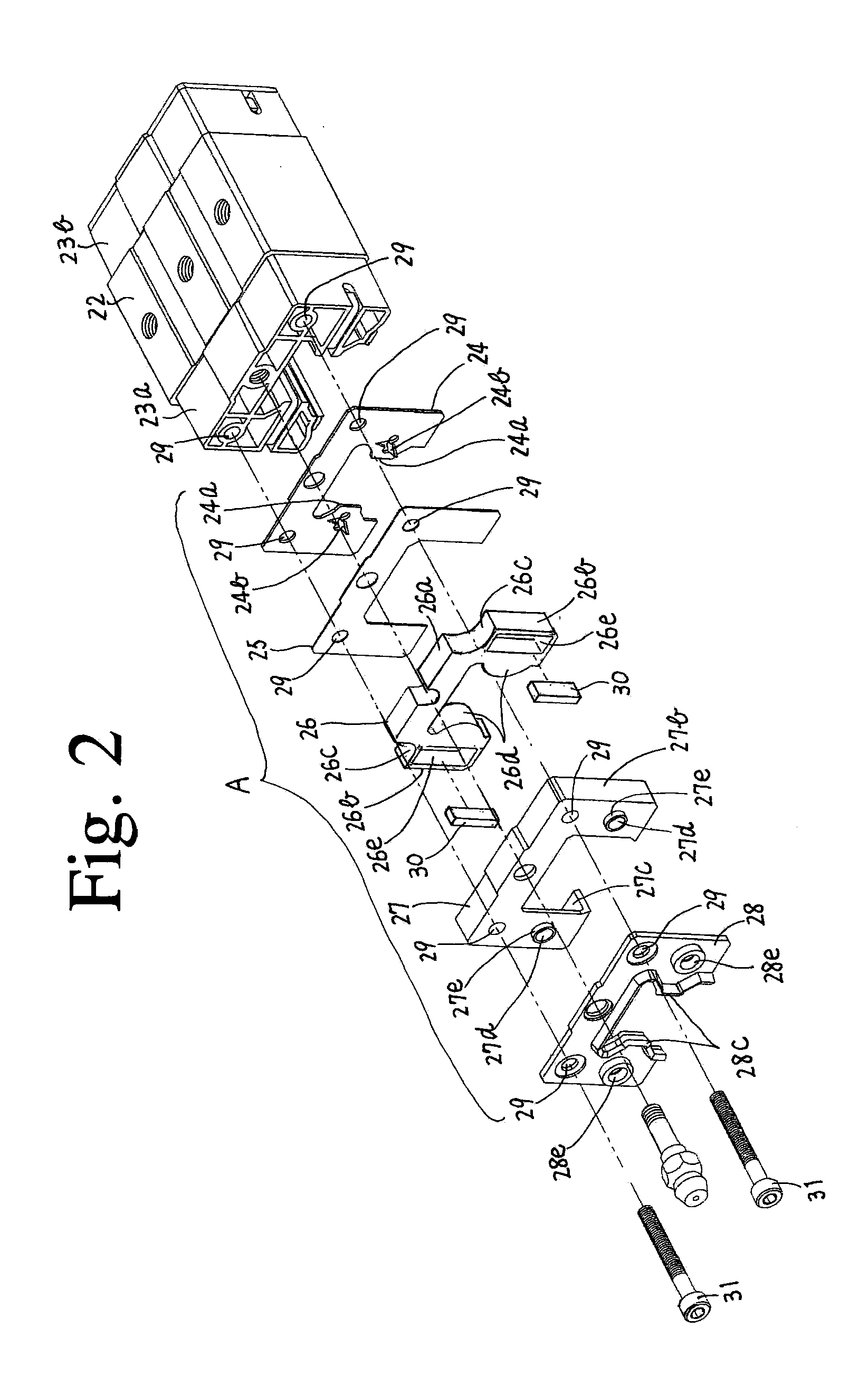
[0058]The slider S straddling the rail R comprises a casing 22 and end caps 23a, 23b which are respectively mounted on the opposing ends of the casing 22. A lubricating member A is mounted on the outward end face of the end cap 23a in FIG. 1. Note that the casing 22 and the end caps 23a, 23b are identical in structure with the conventional ones, each of which has a flat face and side portions extending at right angles to the flat face. Endless circulation passages are provided in the casing 22 and the end caps 23a, 23b to allow a plurality of rolling elements such as rollers to roll and endle...

third embodiment

[0080]The third embodiment increases the volume of the impregnation holding member 30, thus making it possible to increase the amount of lubricant introduced in an additional oiling process.

[0081]Alternatively, an impregnation holding member 30 of the same shape as that in the first embodiment may be mounted in the embedding portion 26e of the member body 26 shown in FIG. 5. In this case, the oil reservoir c is increased in volume. Alternatively, FIG. 7 illustrates a fourth embodiment, in which the impregnation holding member 30 can be mounted in the embedding portion 26e shown in FIG. 5. The impregnation holding member 30 as shown in FIG. 7 has a recess formed in a position corresponding to the position of the oilhole 27d.

[0082]For injection of the lubricant into the lubricating member A thus assembled, for example, the oil injector 32 is slipped into the oiling inlet 28e. At this stage, because of the oil reservoir c created as described earlier, the lubricant injected from the o...

fifth embodiment

[0089]FIG. 9 illustrates a fifth embodiment, in which raceway grooves 33a, 33b corresponding to the raceway sections of the present invention are provided on the rail R, and the balls (not shown) rotatably contained in the slider S roll in the raceway grooves 33a, 33b. In this case, the raceway grooves 33a, 33b are respectively located on opposite sides of each of the upper side corners of the rail R as shown in FIG. 9.

[0090]This involves the necessity of forming each of the impregnation holding members 30 in the fifth embodiment into a shape having a 90-degree bend in such a manner as to completely cover the raceway grooves 33a, 33b on each side of the rail R. When the impregnation holding member 30 is formed in such a shape with a 90-degree bend, it goes without saying that the embedding portion 26e of the member body 26 must be also formed in a shape having a 90-degree bend so as to extend between a point of the coupling portion 26a and a point of each side portion 26b of the mem...


PUM


Abstract

A lubricant can be evenly applied onto raceway faces or raceway grooves of a rail even when fixed to a horizontal, vertical, tilted, or ceiling surface. One or a plurality of embedding portions 26e having a recess or a hole is formed in a member body 26 straddling the rail R. An impregnation holding member 30 holding a lubricant is embedded in the embedding portion. The lubricating member supplies the impregnating lubricant onto the rail raceway faces while making contact with them. Even when the rail is fixed to a horizontal, vertical, tilted or a ceiling surface, the embedding portion of the member body straddling the rail has at least a part maintained in position at a level equal to or higher than the level of at least a part of one of the raceway sections 21a, 21b of the rail located higher relative to the other raceway section.

Description

BACKGROUND OF THE INVENTION[0001]1. Field of the Invention[0002]This invention relates to a linear motion rolling guide unit in which a slider is moving relative to a rail.[0003]2. Description of the Related Art[0004]For a lubricating member and a slider used in such a type of linear motion rolling guide unit, FIG. 10 shows an example of the conventional structure, such as is disclosed in Japanese Patent Application No. 2007-073668 which has been filed by the present applicant. The conventional structure will be described below in detail with reference to FIG. 10.[0005]FIG. 10 illustrates a casing 1 and end caps 2 which are respectively fixedly attached to the opposing ends of the casing 1. Endless circulation passages are provided inside the casing 1 and the end caps 2 for allowing a plurality of rolling elements such as rollers to endlessly circulate therein.[0006]The casing 1 has a flat face 1a and a pair of side portions 1b which extend at right angles to the flat face 1a. As wi...

Claims


Application Information

Patent Timeline
IPC IPC(8): F16C29/04
CPCF16C29/0609F16C33/6648F16C29/0635
Inventor KONDO, MASATOSHI
Owner NIPPON THOMPSON
Why Eureka
Try Eureka