High intensity discharge lamp ballast circuit

a high-intensity discharge and lamp ballast technology, applied in the direction of electric variable regulation, process and machine control, instruments, etc., can solve the problems of high lamp current crest, low efficiency, and reduced lamp li

Active Publication Date: 2007-03-13
INFINEON TECH AMERICAS CORP
View PDF3 Cites 21 Cited by
  • Summary
  • Abstract
  • Description
  • Claims
  • Application Information

AI Technical Summary

Benefits of technology

[0013]In accordance with several advantageous features of the present invention, the control IC according to the present invention provides a 600V full bridge driver, an 800V boost buck driver and control and protection features for completely operating an HID lamp. In accordance with a particular feature offered by the control IC according to the present invention, a timer circuit is provided that permits multiple ignition pulses to be generated for lamp ignition with an interval between ignition attempts being five minutes. The ignition pulses are used to drive the igniter to start or restart the lamp in the case of, for example, a fault condition such as low input voltage. The five-minute wait period permits the HID lamp to cool to a particular temperature to avoid a high voltage hot restrike ignition condition. The control IC also provides an igniter signal that can be directly used to drive an external igniter.

Problems solved by technology

HID lamps enjoy a number of advantages over incandescent lighting and fluorescent lighting, but also have some comparative limitations.
The typical metal halide HID lamp was formerly driven by magnetic ballast, which were not usually optimized for any particular application.
In prior HID lamps, a large open circuit voltage was needed to ignite the lamp, causing a high lamp current crest factor that contributed to diminishing the lifetime of the lamp.
In this circumstance, the ignition voltage can rise to voltages on the order of approximately 25 kV, which can be difficult for an electronic ballast to handle.

Method used


Image

  • High intensity discharge lamp ballast circuit
  • High intensity discharge lamp ballast circuit
  • High intensity discharge lamp ballast circuit

Examples


Embodiment Construction

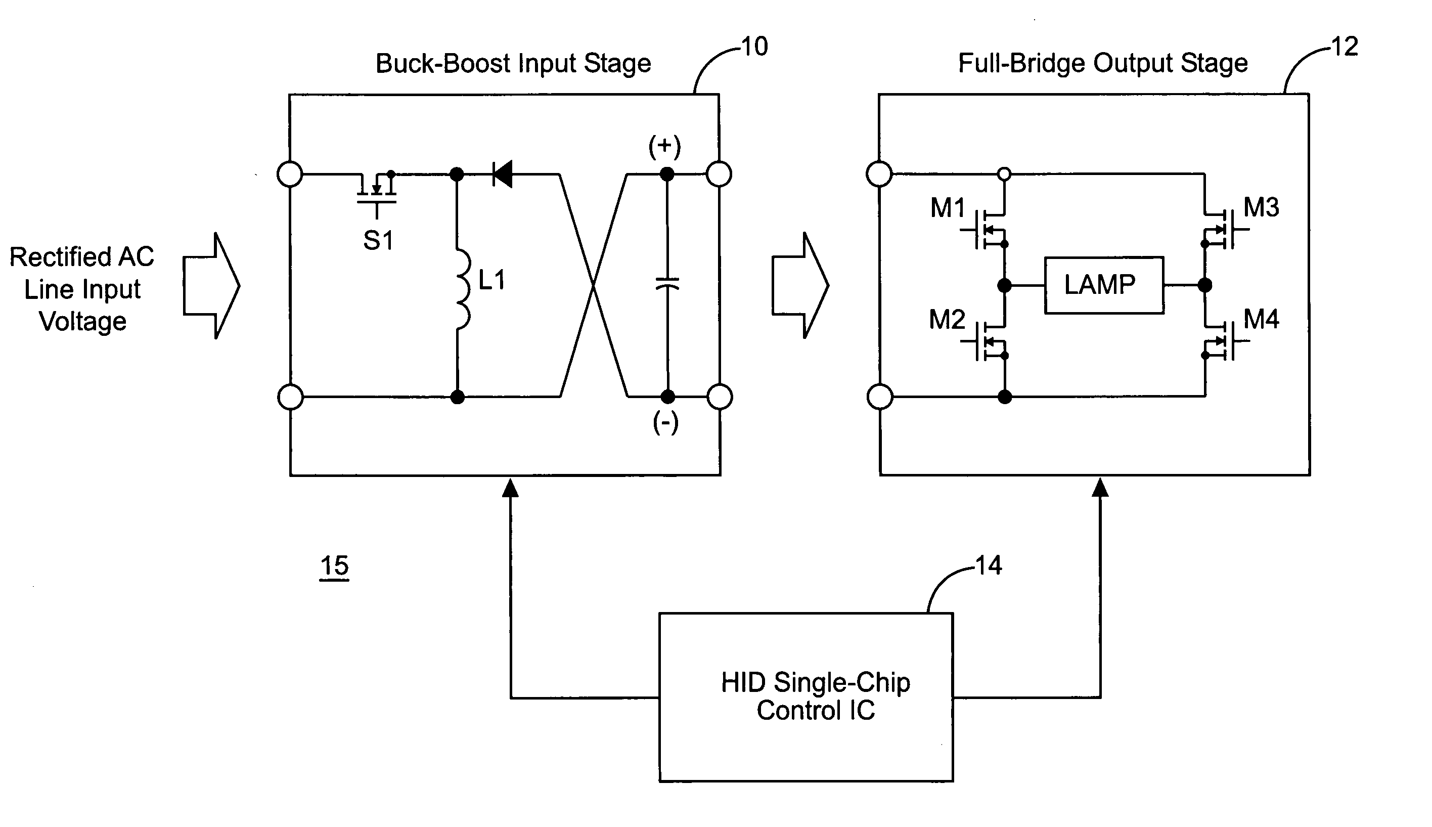
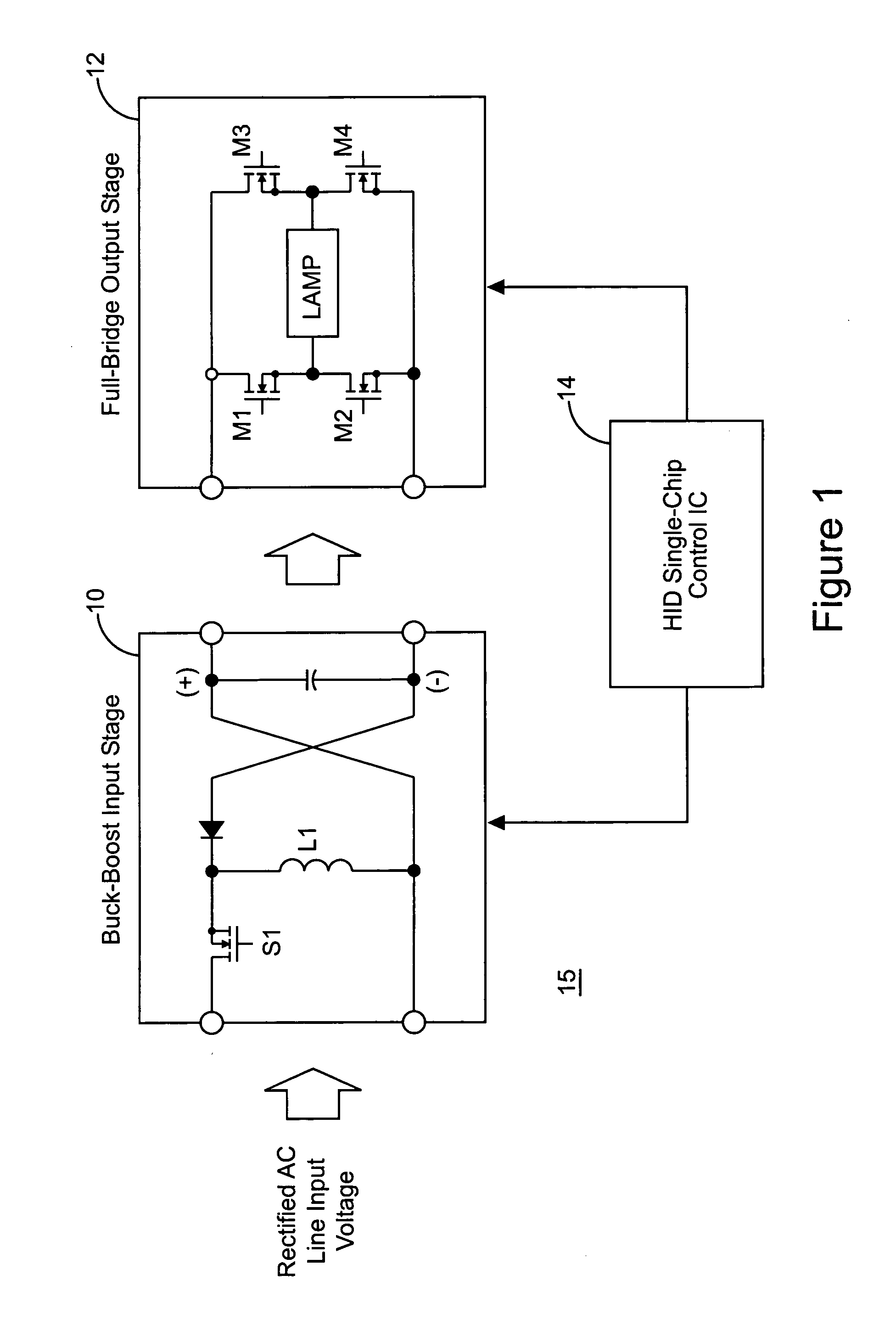
[0023]Referring now to FIG. 1, the present invention is illustrated in a block diagram 15 where the electronic ballast consists of two stages, a buck-boost input stage 10 and a full bridge output stage 12. Full bridge output stage 12 is composed of switches M1–M4, which are switched at a frequency of approximately 200 Hz to avoid acoustic resonance as discussed above. Parameters in the different stages 10 and 12 are sensed and controlled by a control IC 14. Control IC 14 provides gate signals for controlling switches M1–M4 in the full bridge output stage 12 used to drive the HID lamp. Control IC 14 provides a single chip control solution for driving the HID lamp in full bridge output stage 12, while also controlling buck-boost input stage 10 to obtain high power factor and a regulated DC bus.

[0024]Buck-boost input stage 10 includes a switch S1 for operating stage 12 as a buck-boost converter. Control IC 14 provides gating signal for controlling switch S1 and buck-boost input stage 1...


PUM


Abstract

An integrated circuit controls a power converter that includes single stage buck-boost converter and a switching full bridge that may be used to drive an HID lamp. The single stage buck-boost converter reduces the complexity and parts count of the power converter, or electronic ballast, while permitting PFC and DC bus voltage regulation under control of the integrated circuit. The integrated circuit also provides all the drive signals to operate the switching full bridge circuit to maintain constant power on the HID lamp. A wait timer provides an interval of time between restart attempts for the HID lamp to permit the lamp to cool so that high hot restart voltages are avoided. The integrated circuit simplifies the design of power converters and electronic ballasts in particular, while contributing to reducing part count, complexity and cost in conjunction with the single stage buck-boost converter.

Description

RELATED APPLICATIONS[0001]This application is based on and claims benefit of U.S. Provisional Application No. 60 / 455,652, filed Mar. 18, 2003, entitled “High Intensity Discharge Lamp Ballast Circuit,” and U.S. Provisional Application No. 60 / 487,491, filed Jul. 14, 2003, entitled “High Intensity Discharge (HID) Ballast Control Circuit” upon both of which a claim of priority is hereby made.BACKGROUND OF THE INVENTION[0002]1. Field of the Invention[0003]The present invention relates generally to electronic lamp ballasts, and relates more particularly to an electronic lamp ballast and control for a high intensity discharge lamp.[0004]2. Description of Related Art[0005]High intensity discharge (HID) lamps have been in use for a number of years in a variety of lighting applications. Four types of HID lamps are typically used in practice, including mercury vapor, low pressure sodium, high pressure sodium and metal halide. HID lamps enjoy a number of advantages over incandescent lighting an...

Claims


Application Information

Patent Timeline
Patent Type & Authority Patents(United States)
IPC IPC(8): G05F1/24H05B41/288
CPCH05B41/2886H05B41/2888Y02B20/206Y02B20/202H05B45/375H05B45/38Y02B20/00Y02B20/30G05F1/10H05B41/26
Inventor RIBARICH, THOMAS J.CONTENTI, CECILIASEKINE, MASASHI
Owner INFINEON TECH AMERICAS CORP
Why Eureka
Try Eureka