Cut-away cutting tool

Active Publication Date: 2019-09-26
HONDA MOTOR CO LTD
View PDF0 Cites 0 Cited by
  • Summary
  • Abstract
  • Description
  • Claims
  • Application Information

AI Technical Summary

Benefits of technology

[0014]Further, it is preferable that the peeling blade portion be slanted to become thicker in a direction away from the flat conductor wire. The insulating coating which is peeled off by the tip blade of the peeling blade portion from the electrical conductor is turned up along the slant. Therefore, it becomes easy to cut away the insulating coating.
[0015]The peeling blade portion may gradually become wider as the peeling blade portion comes close to the flat conductor wire. This is because the configuration of the peeling blade portion enables the turning-up to proceed further smoothly.
[0016]According to the present invention, the cut-away cutting tool is configured to provide on the

Problems solved by technology

This gives rise to a problem that the peeling device is e

Method used


Image

  • Cut-away cutting tool
  • Cut-away cutting tool
  • Cut-away cutting tool

Examples


Example

[0027]With reference to the accompanying drawings, a preferred embodiment of a cut-away cutting tool according to the present invention will be described in detail based on a preferred embodiment.

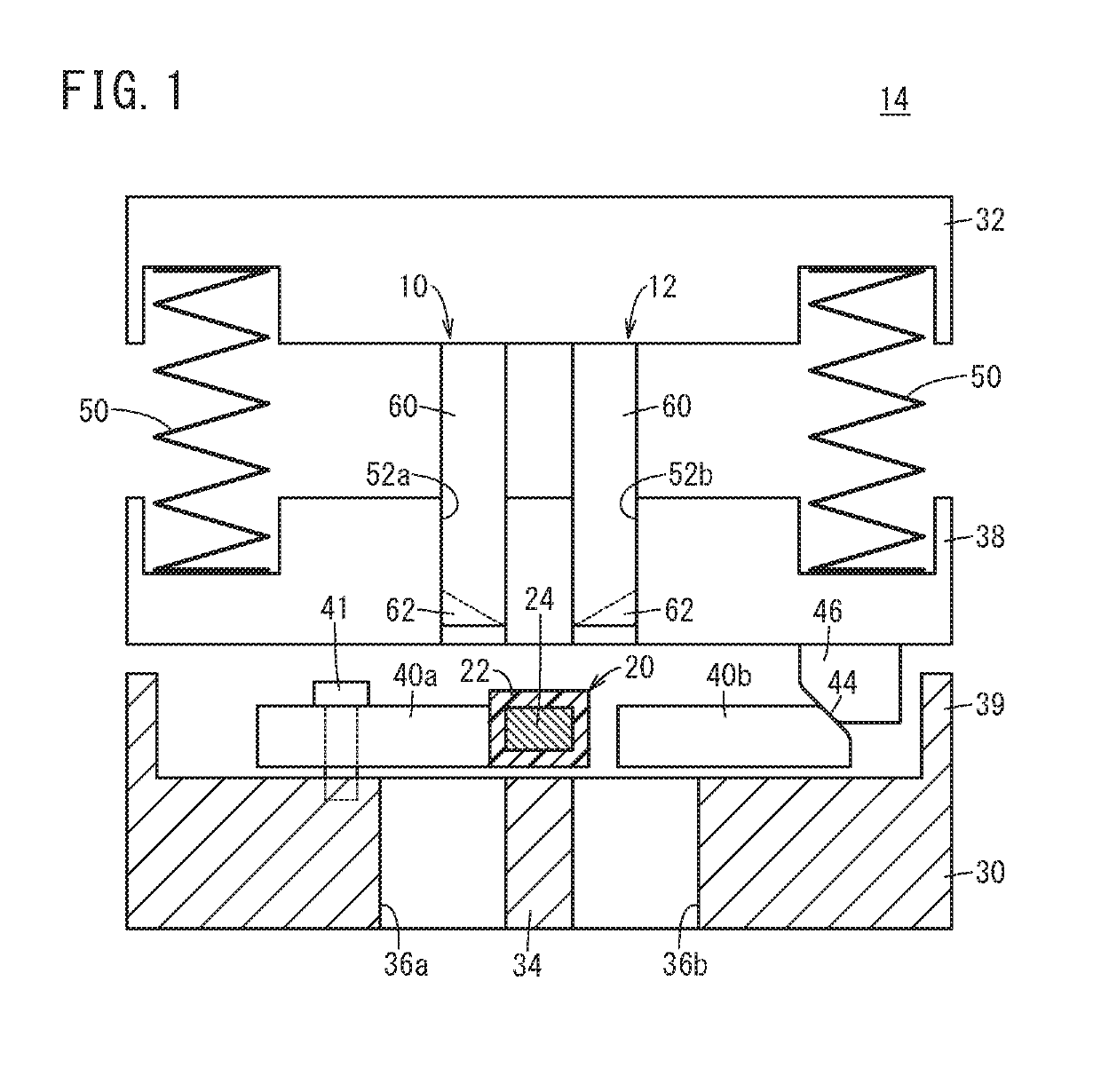
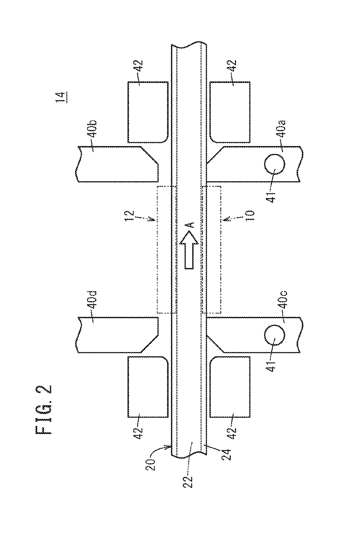
[0028]FIG. 1 is a schematic sectional view of a principal portion of a peeling device 14 equipped with a left cut-way cutting tool 10 and a right cut-way cutting tool 12 which are each a cut-way cutting tool according to the present embodiment. This peeling device 14 is used to expose an electric conductor 24 by cutting away an insulating coating 22 from a flat conductor wire 20.

[0029]The electric conductor 24 is formed of, for example, copper, aluminum or the like and takes a substantially rectangular shape in a cross section perpendicular to the extending direction. On the other hand, the insulating coating 22 is formed of, for example, a resin or the like showing electric insulation property. The insulating coating 22 is formed in a substantially rectangular frame shape in a cross sectio...


PUM


Abstract

A cut-away cutting tool has two slit forming blade portions and a peeling blade portion interposed between the two slit forming blade portions. The two slit forming blade portions respectively form slits on an insulating coating of a flat conductor wire. On the other hand, the peeling blade portion peels off a portion of the insulating coating between the slits formed by the two slit forming blade portions.

Description

CROSS-REFERENCE TO RELATED APPLICATION[0001]This application is based upon and claims the benefit of priority from Japanese Patent Application No. 2018-058109 filed on Mar. 26, 2018, the contents of which are incorporated herein by reference.BACKGROUND OF THE INVENTIONField of the Invention[0002]The present invention relates to a cut-away cutting tool for cutting away an insulating coating from a flat conductor wire.Description of the Related Art[0003]Flat conductor wires in which electric conductors are coated with insulating coatings have been in wide use as, for example, winding wires or the like for electromagnetic coils of rotary electric machines. Here, the insulating coatings are of insulation property, and therefore, it is necessary to remove the insulating coatings from portions at which the electromagnetic coils are electrically connected to electronic elements or the like.[0004]Such insulating coatings are removed under the operation of a peeling device. Japanese Laid-Ope...

Claims


Application Information

Patent Timeline
IPC IPC(8): H02G1/12H02K15/04
CPCH02K15/04H02G1/127H02G1/126H02G1/1256H02G1/1285
Inventor ONDA, HIDEAKIMOTOJIMA, TAKAYUKIMASAI, KENJIMIYASHITA, KEITA
Owner HONDA MOTOR CO LTD
Why Eureka
Try Eureka