Transfer unit and image forming apparatus
- Summary
- Abstract
- Description
- Claims
- Application Information
AI Technical Summary
Benefits of technology
Problems solved by technology
Method used
Image

Examples
first embodiment
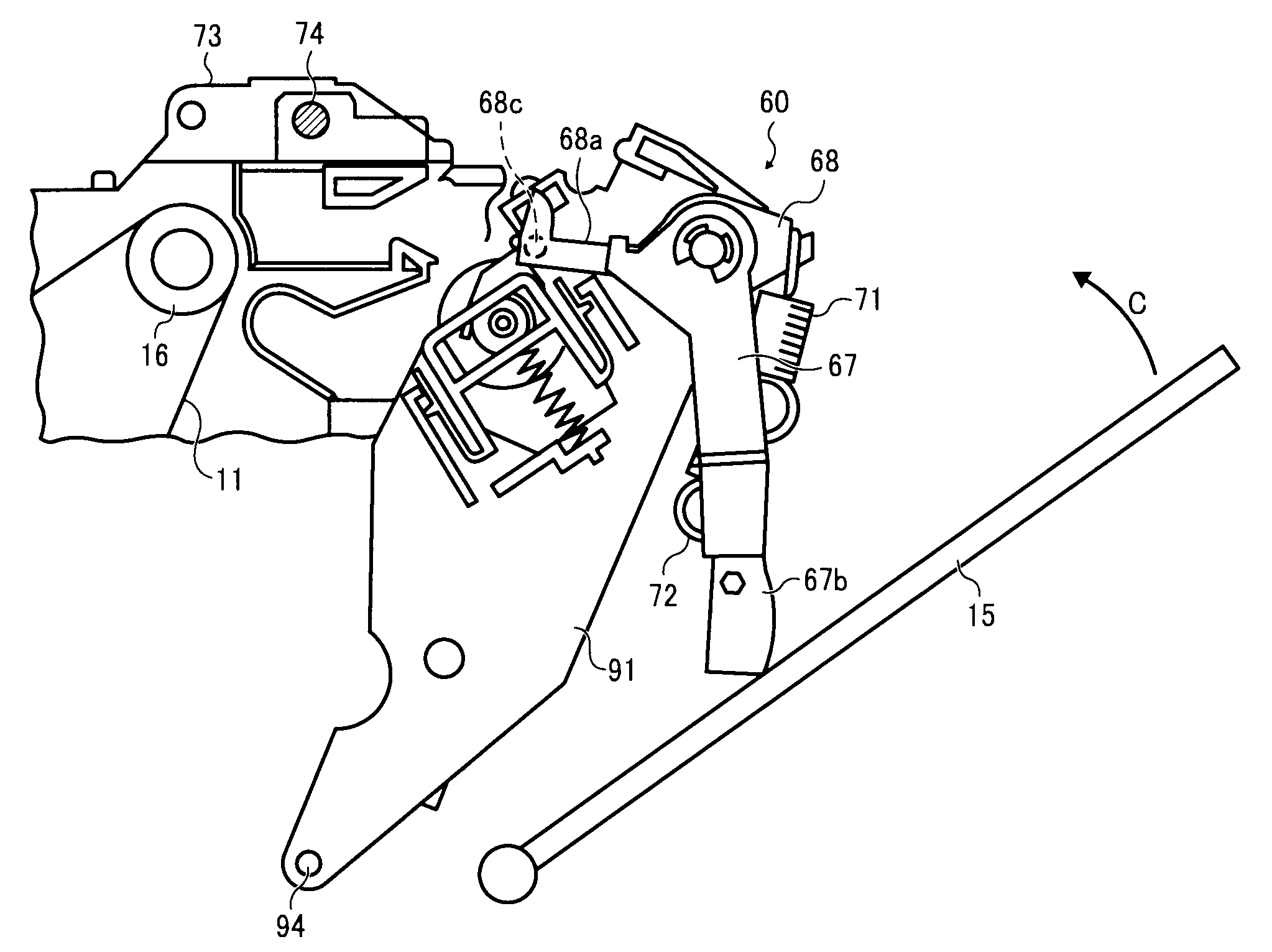
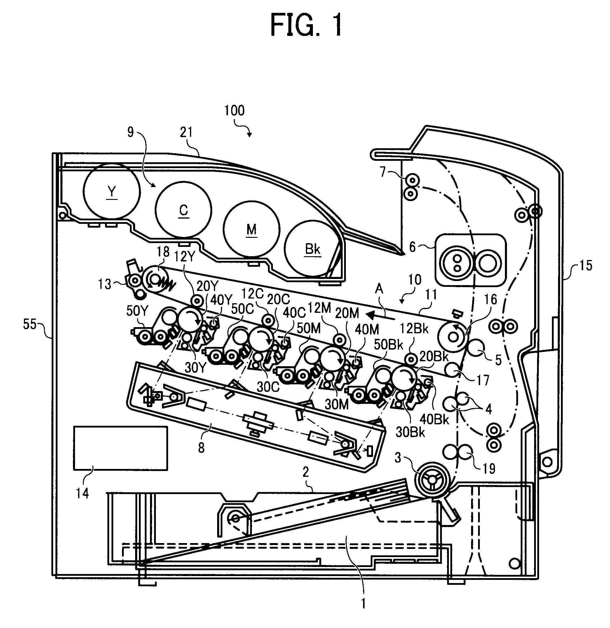
[0072]Hereinafter, an embodiment of the present invention will be explained, referring to the drawings. First, a first embodiment will be explained, based on FIG. 1 or FIG. 12. The same part uses the same symbol. FIG. 1 is a color printer as an image forming apparatus. As shown in FIG. 1, a color printer 100 includes a transfer belt unit 10 having an intermediate transfer belt 11 as an image bearer and four image stations. Each of the image stations has photoreceptor drums 20Y, 20C, 20M and 20Bk, and exclusive chargers 30Y, 30C, 30M and 30Bk, image developers 50Y, 50C, 50M and 50Bk, cleaners 40Y, 40C, 40m and 40Bk around the photoreceptor drums.
[0073]The intermediate transfer belt 11 is supported by a support rollers 16, 17 and 18, and the support roller 16 faces a second transfer roller 5 and the support roller 18 faces an intermediate transfer belt cleaner.
[0074]A numeral 9 is a toner bottle container including a toner bottle filled with a yellow toner (Y), a toner bottle filled w...
second embodiment
[0120]FIG. 13 is a The same parts have the same symbols in the above-mentioned embodiment. Explanations of the constitutions and functions already explained are omitted and only the main parts will be explained unless particularly necessary (Other embodiments are same).
[0121]In this embodiment, a lever member 85 is a unit body having a compressed spring 86 as an elastic member formed on a contact part 85b, which is a cushion when engaging with the stud 74. In FIG. 13, the both side unit 15 is almost upright.
[0122]A numeral 85a is the engaging part 68a and a numeral 85c is the projection 68c in the above-mentioned embodiment.
[0123]The lever member 66 in the first embodiment may be a unit body as the lever member 85 is.
third embodiment
[0124]FIG. 14 is a
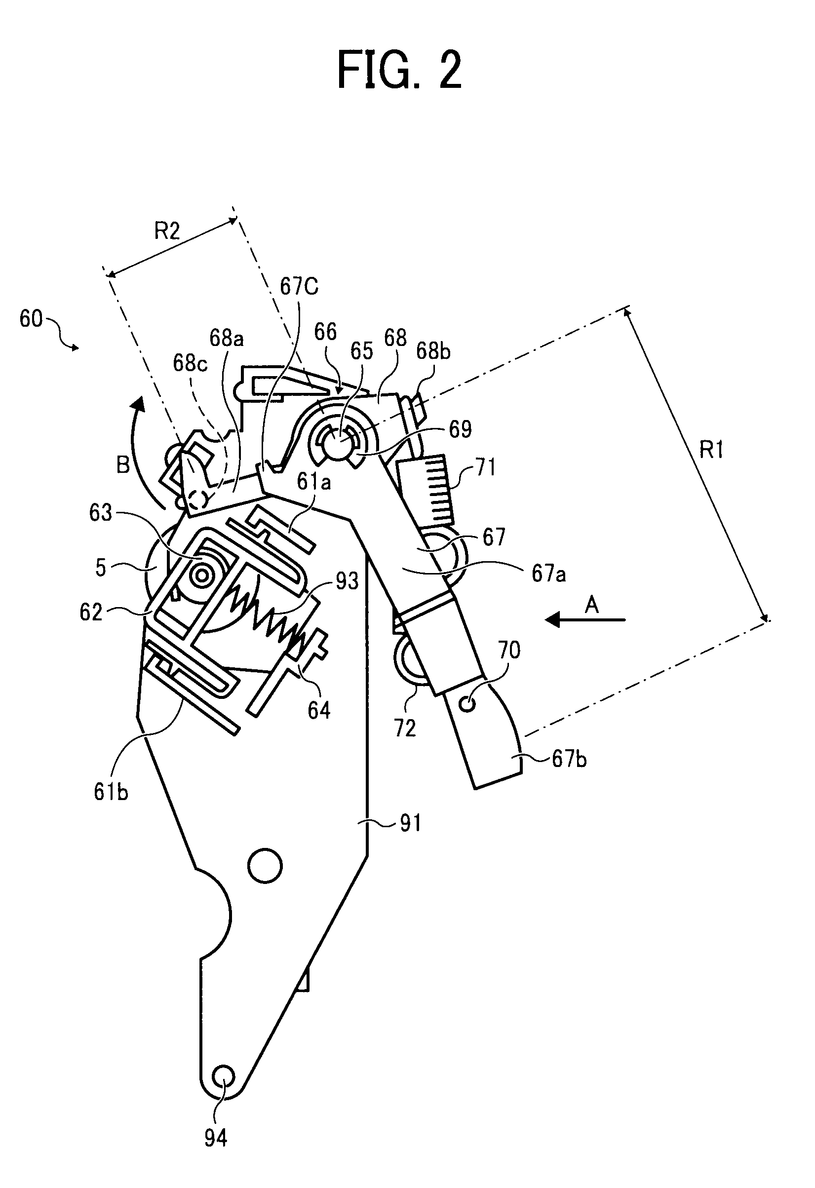
[0125]In this embodiment, the contact position of the contact part 67b of the lever member 66 to the both side unit 15 is adjustable. A long hole 67a-1 extending in the longitudinal direction of the first lever 67a is formed at the bottom end thereof. After the position of the contact part 67b is adjusted, it is fixed with a bolt 70 and a nut (not shown).
[0126]Thus, the contact position of the contact part 67b to the both side unit 15 and the setting force are adjustable, and which is applicable when the contact position with the both side unit 15 needs adjustment.
[0127]As a matter of course, the long hole ma be formed at the contact part 67b. The contact part 67b can be screwed in the first lever body 67a and the position can be adjusted with a screw-in quantity.
[0128]In each of the above-mentioned embodiments, the second transfer unit 60 is turnably formed on the image forming apparatus 55. Even when the second transfer unit 60 is turnably formed on the both side...
PUM
 Abstract
Description
Claims
Application Information
 - Generate Ideas
- Intellectual Property
- Life Sciences
- Materials
- Tech Scout
- Unparalleled Data Quality
- Higher Quality Content
- 60% Fewer Hallucinations
Browse by: Latest US Patents, China's latest patents, Technical Efficacy Thesaurus, Application Domain, Technology Topic, Popular Technical Reports.
© 2025 PatSnap. All rights reserved.Legal|Privacy policy|Modern Slavery Act Transparency Statement|Sitemap|About US| Contact US: help@patsnap.com