Intelligent orthotic insoles

a technology of orthotics and insoles, applied in the field of orthotic insoles, can solve the problem that the body incorporating the sensor does not provide any other function, and achieve the effect of reducing the risk of injury

Inactive Publication Date: 2010-01-07
ESOLES LLC
View PDF31 Cites 114 Cited by
  • Summary
  • Abstract
  • Description
  • Claims
  • Application Information

AI Technical Summary

Problems solved by technology

However, each seems to require a separate element to provide the pressure measurements typically without an orthotic device.
The body incorporating th...

Method used


Image

  • Intelligent orthotic insoles
  • Intelligent orthotic insoles
  • Intelligent orthotic insoles

Examples


Embodiment Construction

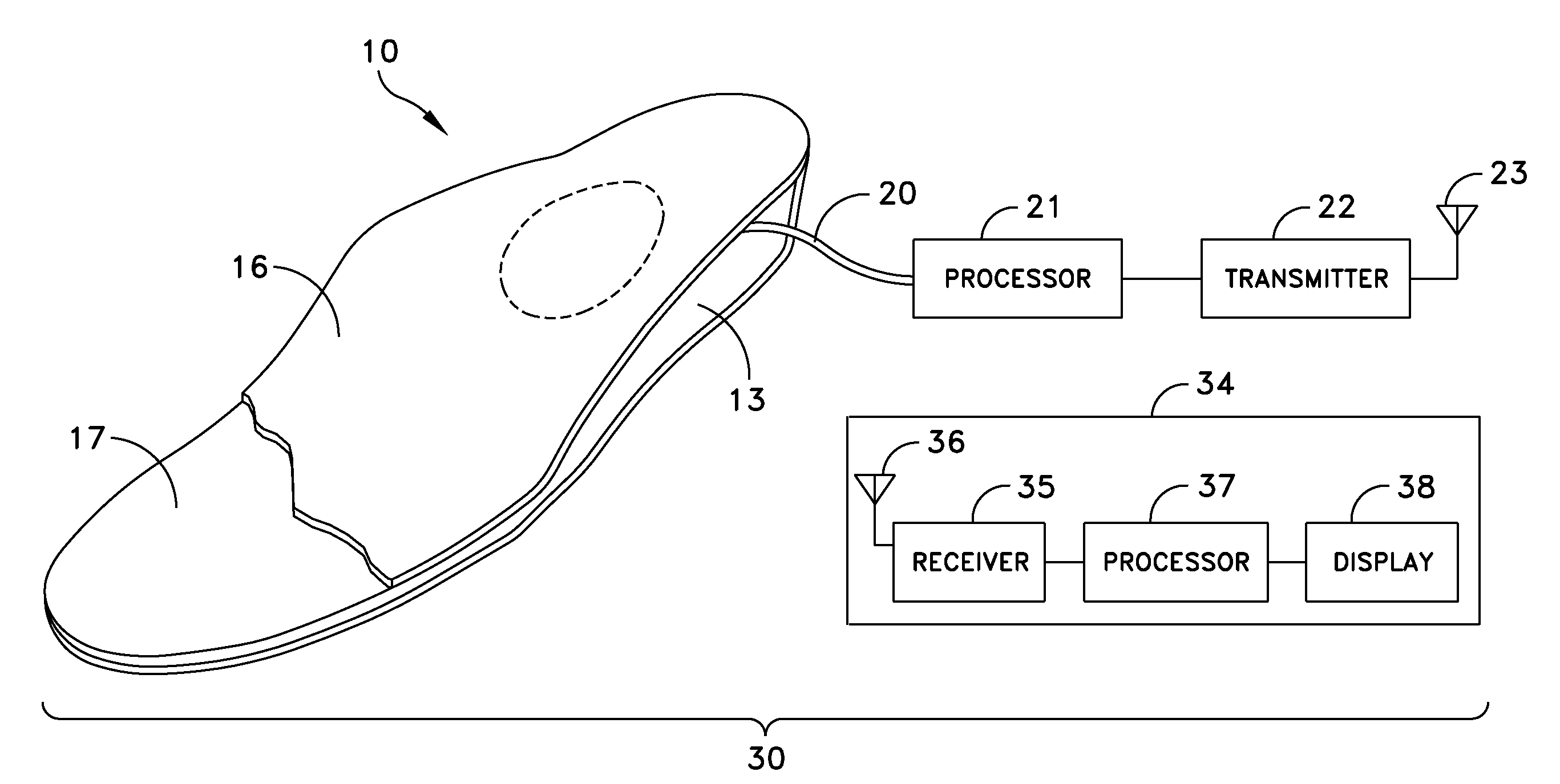
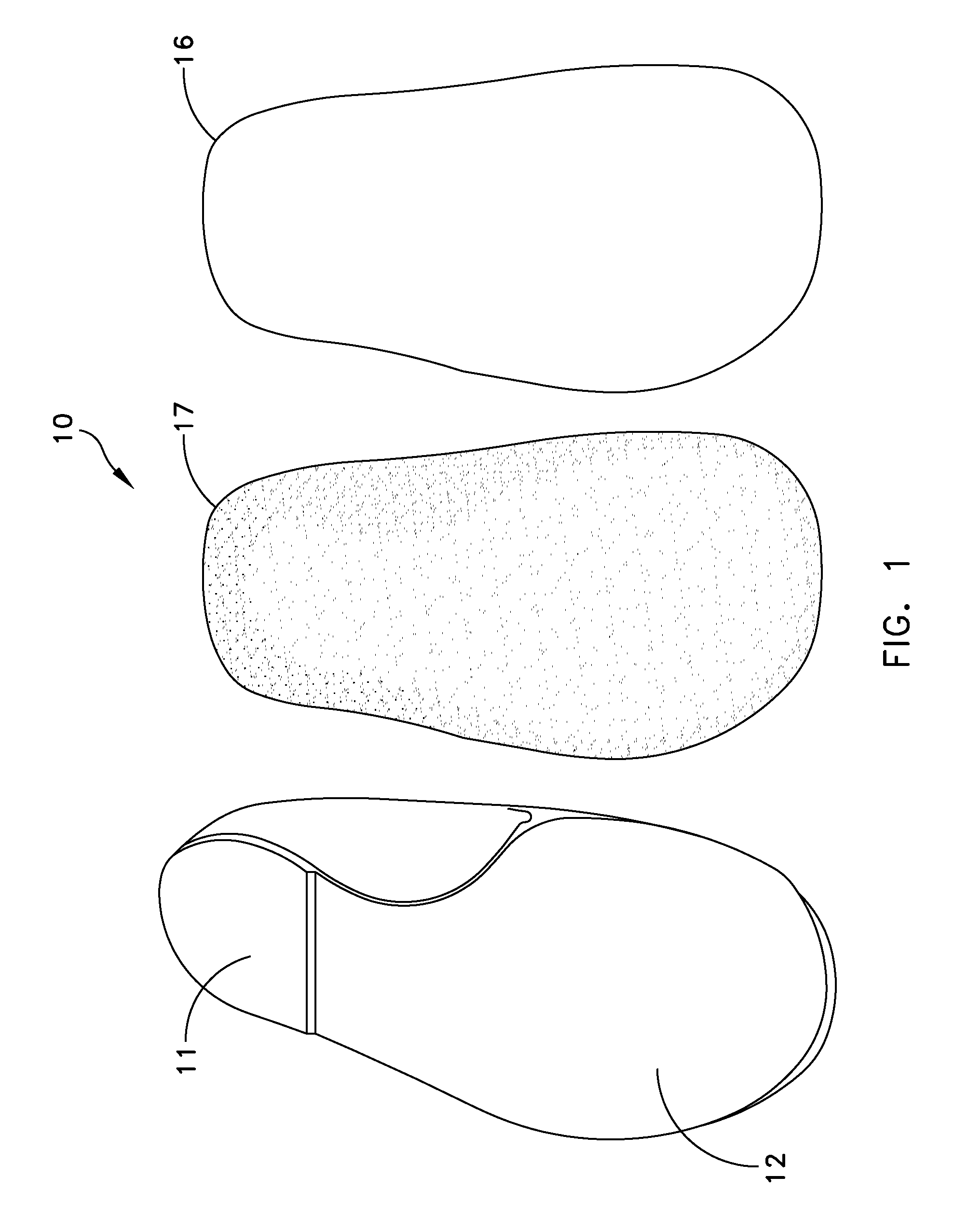
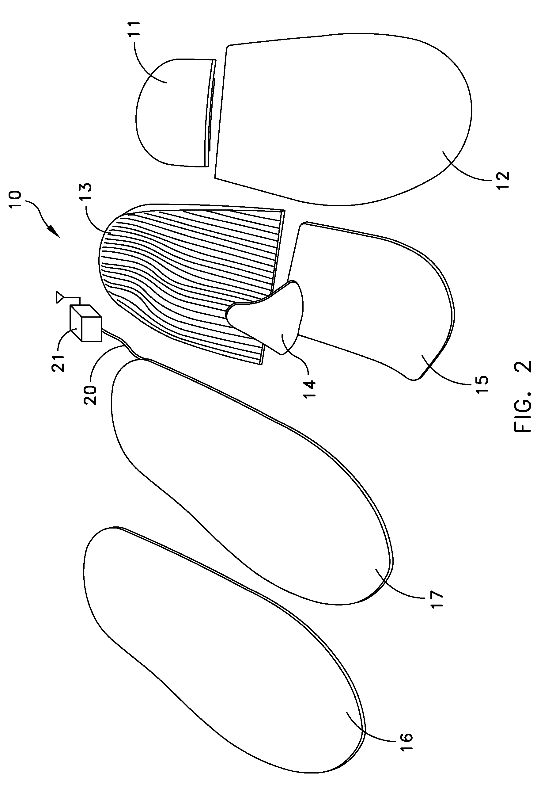
[0028]The above-identified U.S. Pat. No. 7,392,559 describes the construction of an orthotic insert without this invention. FIGS. 1 and 2 depict an intelligent orthotic insole 10 constructed in accordance with this invention with a heel post stabilizer 11 and a midfoot stabilizer 12 at a bottom layer. An orthotic 13 is constructed in accordance with U.S. Pat. No. 7,392,559 and lies on top of the stabilizers 11 and 12. The insole 10 may also include a metatarsal support 14 and a forefoot post 15. A top cover 16 overlies the entire orthotic insole 10. As known, the orthotic insert itself has some thickness in order to allow the machining to occur.

[0029]FIGS. 1 and 2 also depict an orthotic insole 10 with an integral sensor pad 17 that is a capacitive force sensing matrix that provides information about the magnitude and position of the pressure to produce a three-dimensional pressure map. For integration into an insole 10, the sensor 17 in FIGS. 1 and 2 preferably forms a flexible tac...


PUM


Abstract

An intelligent insole for generating time sensitive information about the pressure on the foot. The insole includes a custom-made, semi-custom or generically sized orthotic component. The orthotic is laminated with a top cover and an intermediate pressure sensor having an array of capacitive pressure sensors. Signal processing equipment may be embedded in the insole or placed locally with the insole as on the side of a shoe. The processor also can connect to a wireless transmitter for relaying the information to a remote site.

Description

CROSS REFERENCE TO RELATED APPLICATION [0001]This application claims benefit from U.S. Provisional Patent Application Ser. No. 61 / 020,598 filed Jan. 11, 2008 for an Intelligent Orthotic Insole.[0002]This application cross references U.S. patent application Ser. No. 11 / 116,738 filed Apr. 28, 2005 for a Method and Apparatus for Manufacturing Custom Orthotic Footbeds and assigned to the same assignee as this invention, which application was granted on Jul. 1, 2008 as U.S. Pat. No. 7,392,559.BACKGROUND OF THE INVENTION [0003]1. Field of the Invention[0004]This invention generally relates to orthotic insoles and more particularly to an insole that dynamically produces pressure maps of an individual's foot.[0005]2. Description of Related Art[0006]Over the years greater emphasis has been placed on the need for athletic performance and individual exercise. Athletes need to understand the ramifications of change in their routines. For example, information about the pressure on the bottom of ...

Claims


Application Information

Patent Timeline
IPC IPC(8): A61B5/103A43B13/38G08B1/08
CPCA43B3/0005A43B17/00A43D1/02A61B2562/046A61B5/1036A61B2562/0247A61B5/0002A43B7/28A43B3/34A43B3/44
Inventor SON, JAEHINSHAW, GLEN D.ABLES, DAVID
Owner ESOLES LLC
Why Eureka
Try Eureka