Eureka AIR delivers breakthrough ideas for toughest innovation challenges, trusted by R&D personnel around the world.

Crimp fitting for corrugated stainless steel tubing

a technology of stainless steel tubing and crimping, which is applied in the direction of hose connection, manufacturing tools, mechanical equipment, etc., can solve the problems of radial compression of at least one corrugated tubing, and achieve the effect of reliable sealing

Active Publication Date: 2010-01-14
TITEFLEX
View PDF43 Cites 22 Cited by
  • Summary
  • Abstract
  • Description
  • Claims
  • Application Information

AI Technical Summary

Benefits of technology

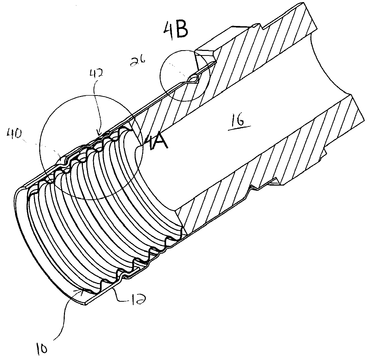
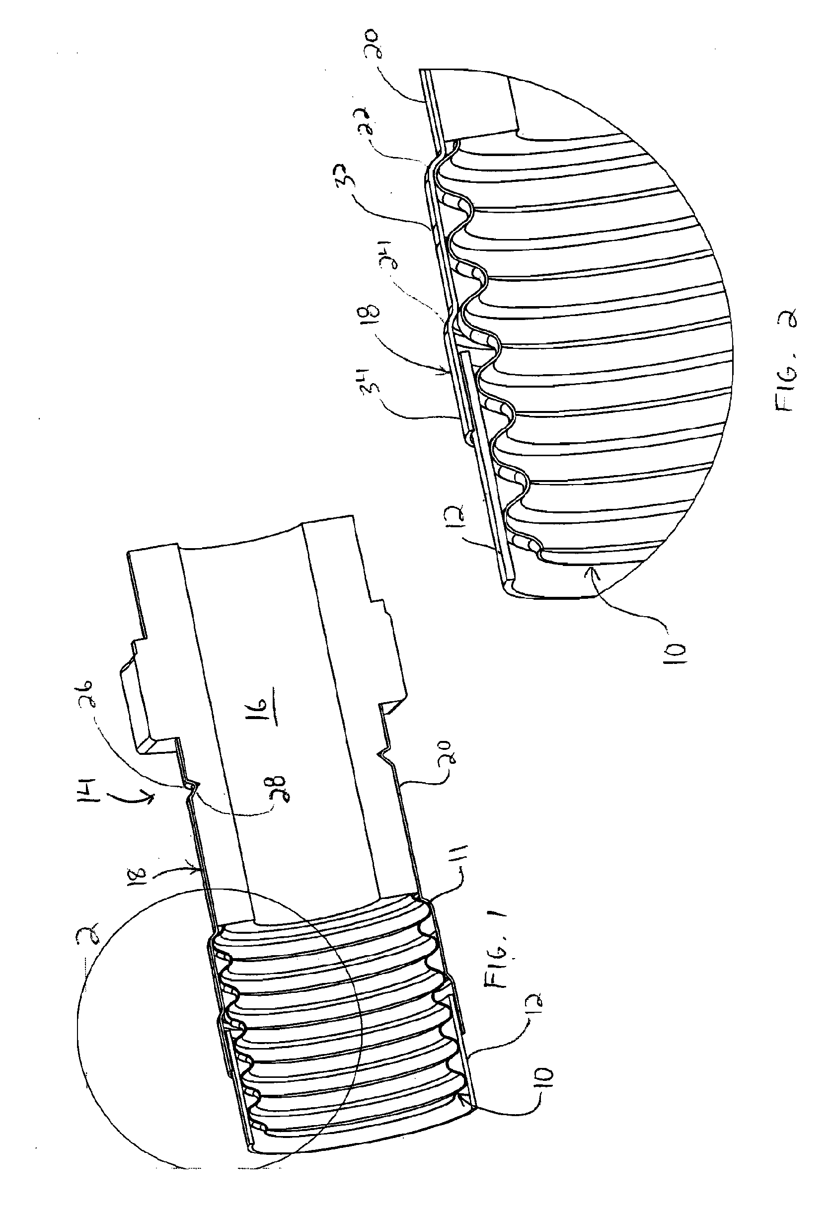
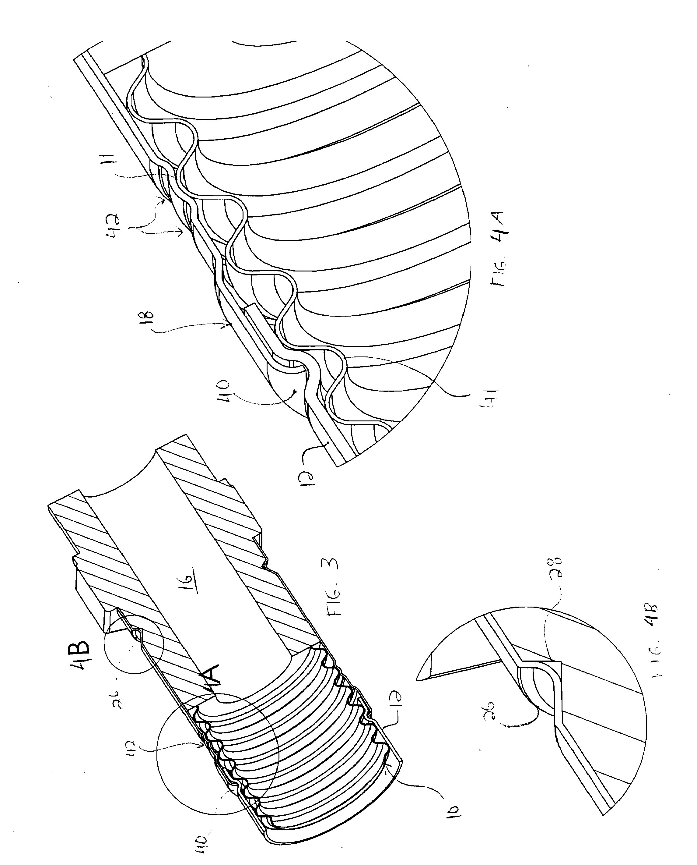
[0009]A fitting incorporating a crimp sealing device and a method for forming a seal between a length of corrugated tubing and the fitting are disclosed. The tubing can be corrugated stainless steel tubing (CSST) commonly used in gas and liquid piping systems. The tubing can be at least partially covered with a jacket. At least one crimp seal preferably is formed between the tubing and / or jacket, and the fitting. As used herein, the term “crimp sealing device” refers to one or more components made of metal or another material that are crimped and sealed together. According to the present invention, a suitable seal can be formed without requiring excessive torque to form the seal. Instead, a predetermined sealing pressure per unit area preferably is applied to a sealing interface. A crimp seal formed according to the present invention generally is more tolerant to different tubing cuts, whereas the prior art sealing technique of collapsing or crushing the corrugated tubing by use of a nut in conjunction with an adapter generally requires a clean cut in order to form a reliable seal.

Problems solved by technology

A sealing crimp applied radially also can result in radial compression of at least one corrugation of the tubing, either with or without the sealing area.

Method used


Image

  • Crimp fitting for corrugated stainless steel tubing
  • Crimp fitting for corrugated stainless steel tubing
  • Crimp fitting for corrugated stainless steel tubing

Examples


Embodiment Construction

[0042]A fitting incorporating a crimp sealing device and a method for forming a seal between a length of corrugated tubing and the fitting are disclosed. The tubing can be corrugated stainless steel tubing (CSST) commonly used in gas and liquid piping systems. The tubing can be at least partially covered with a jacket. According to the present invention, at least one crimp seal is formed between the tubing and / or jacket, and the fitting. Therefore, a suitable seal can be formed between the tubing and / or jacket, and the fitting, without requiring excessive torque to form the seal. Optionally, one or more corrugations of the tubing may be collapsed or crushed axially and / or radially through application of radial force to form a crimp seal, but axial and / or radial collapsing or crushing of one or more corrugations is not required according to the present invention.

[0043]According to the present invention, various types of crimp sealing devices can be used. One type of crimp sealing dev...


PUM

PropertyMeasurementUnit
pressuresaaaaaaaaaa
lengthaaaaaaaaaa
shapeaaaaaaaaaa

Abstract

A fitting incorporating a crimp sealing device and a method of forming a seal between a length of corrugated tubing and the fitting are provided. A sealing crimp is formed over at least one corrugation of the tubing, where the sealing crimp can utilize a preformed bend or bulge to form a crimp and seal. Alternatively, the sealing crimp can apply pressure radially against an outer sleeve of the fitting, such that at least one corrugation of the tubing is compressed axially or radially to form a primary seal. The outer sleeve also can include one or more gaskets arranged between the outer sleeve and the tubing for forming a secondary seal. An inner sleeve can be received radially inside the outer sleeve, and one or more gaskets can be arranged between the inner sleeve and the tubing. Further, a jacket crimp can be applied against an end of the sleeve member to contact a jacket that at least partially covers the tubing.

Description

CROSS-REFERENCE TO RELATED APPLICATION[0001]This application claims the benefit of copending application U.S. Provisional Application Ser. No. 60 / 841,877 filed on Aug. 31, 2006, the disclosure of which is expressly incorporated herein by reference in its entirety.FIELD OF INVENTION[0002]The present invention relates to gas and liquid piping systems, and more particularly to a fitting incorporating a crimp sealing device and method for forming a seal between a length of corrugated tubing and the fitting.BACKGROUND OF THE INVENTION[0003]Gas and liquid piping systems which utilize corrugated stainless steel tubing (“CSST”) and fittings are known. Such piping systems can be designed for use in combination with elevated gas pressures of up to about 0.03 megapascals (MPa) or more, and provide advantages over traditional rigid black iron piping systems in terms of ease and speed of installation, elimination of onsite measuring, and reduction in the need for certain fittings such as elbows,...

Claims


Application Information

Patent Timeline
Patent Type & Authority Applications(United States)
IPC IPC(8): F16L33/00F16L55/00
CPCF16L13/142F16L25/0036Y10T29/49927F16L33/2073F16L33/207
Inventor DUQUETTE, SCOTTKELLAR, FRANZCROWDER, HAROLDEOWSAKUL, VANWIJAKCOPPOLA, BRIAN
Owner TITEFLEX
Why Eureka
Eureka Blog
Learn More