Visualizing and Manipulating Digital Models for Dental Treatment

a digital model and orthodontic technology, applied in the field of dentistry, can solve the problems of manually applying such bends, difficult for a human being to accurately develop a visual three-dimensional image of an orthodontic structure, and difficult to accurately estimate three-dimensional wire bends, etc., to achieve accurate perception of relative positions of various parts, easy, fast, and less expensive

Inactive Publication Date: 2010-01-14
ALIGN TECH
View PDF4 Cites 94 Cited by
  • Summary
  • Abstract
  • Description
  • Claims
  • Application Information

AI Technical Summary

Benefits of technology

[0029]Using hand gestures to instruct a computer to manipulate a digital dental model may, in some variations, be easier, faster, and less expensive than using a conventional mouse and / or keyboard to interact with the computer. Stereoscopically viewing a three-dimensional digital model, rather than viewing a flat representation of the digital model, may also allow easier, faster, and less expensive manipulation of the digital model in some variations because, for example, the stereoscopic view may allow a user to more accurately perceive the relative positions of various portions of the digital model.

Problems solved by technology

Unfortunately, in the oral environment, it is difficult for a human being to accurately develop a visual three-dimensional image of an orthodontic structure due to the limitations of human sight and the physical structure of a human mouth.
In addition, it is difficult to accurately estimate three-dimensional wire bends (with accuracy within a few degrees) and to manually apply such bends to a wire.
Further, it is hard to determine an ideal bracket location to achieve the desired orthodontic structure based on the mental images.
It is also extremely difficult to manually place brackets in what is estimated to be the ideal location.
As a result of multiple wire changes, subject discomfort and cost are increased.
That is, when an appliance is first worn by the subject, certain of the teeth will be misaligned relative to an undeformed geometry of the appliance cavity.

Method used


Image

  • Visualizing and Manipulating Digital Models for Dental Treatment
  • Visualizing and Manipulating Digital Models for Dental Treatment
  • Visualizing and Manipulating Digital Models for Dental Treatment

Examples


Embodiment Construction

in conjunction with the accompanying drawings that are first briefly described.

BRIEF DESCRIPTION OF THE DRAWINGS

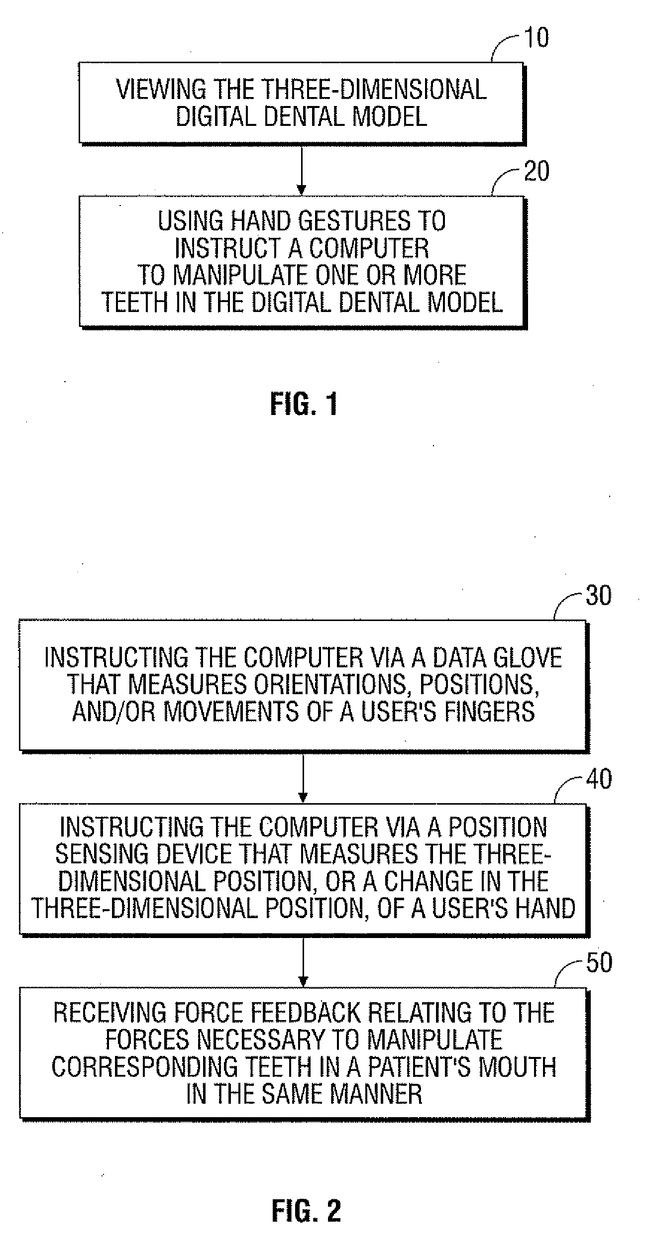
[0031]FIG. 1 shows a flow chart for an exemplary process for visualizing and manipulating a digital dental model.

[0032]FIG. 2 shows a flow chart for using hand gestures to instruct a computer to manipulate one or more teeth in a digital dental model according to some variations of the exemplary process of FIG. 1.

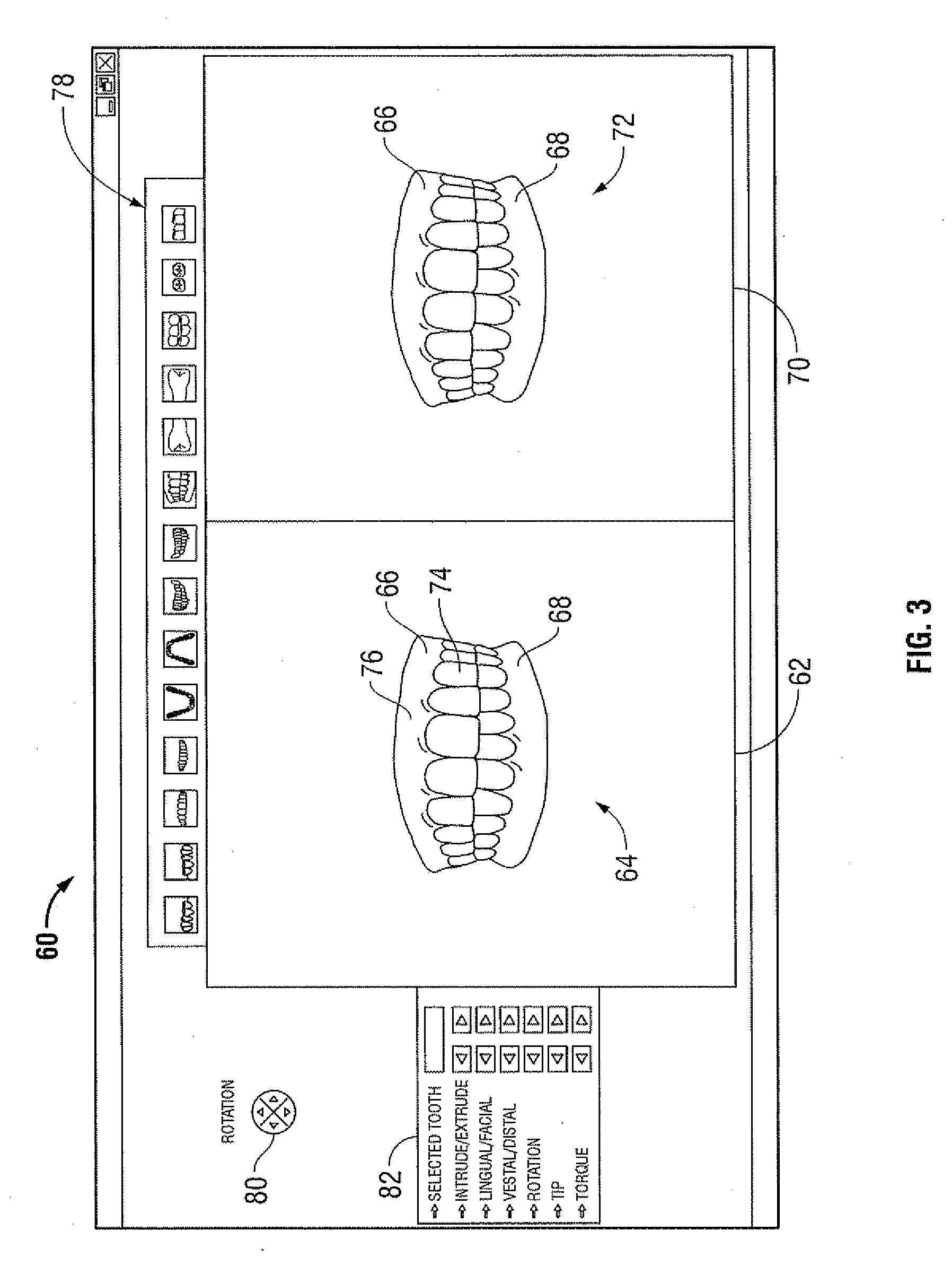
[0033]FIG. 3 shows an example of a user interface for displaying a digital representation of a subject's tooth arches. In this example, two windows are provided to display both a pre-modified tooth arch (shown in the left window) and a modified tooth arch (shown in the right window) in a side-by-side manner.

[0034]FIG. 4 shows a flow chart for an exemplary process for fabricating dental aligners as described herein.

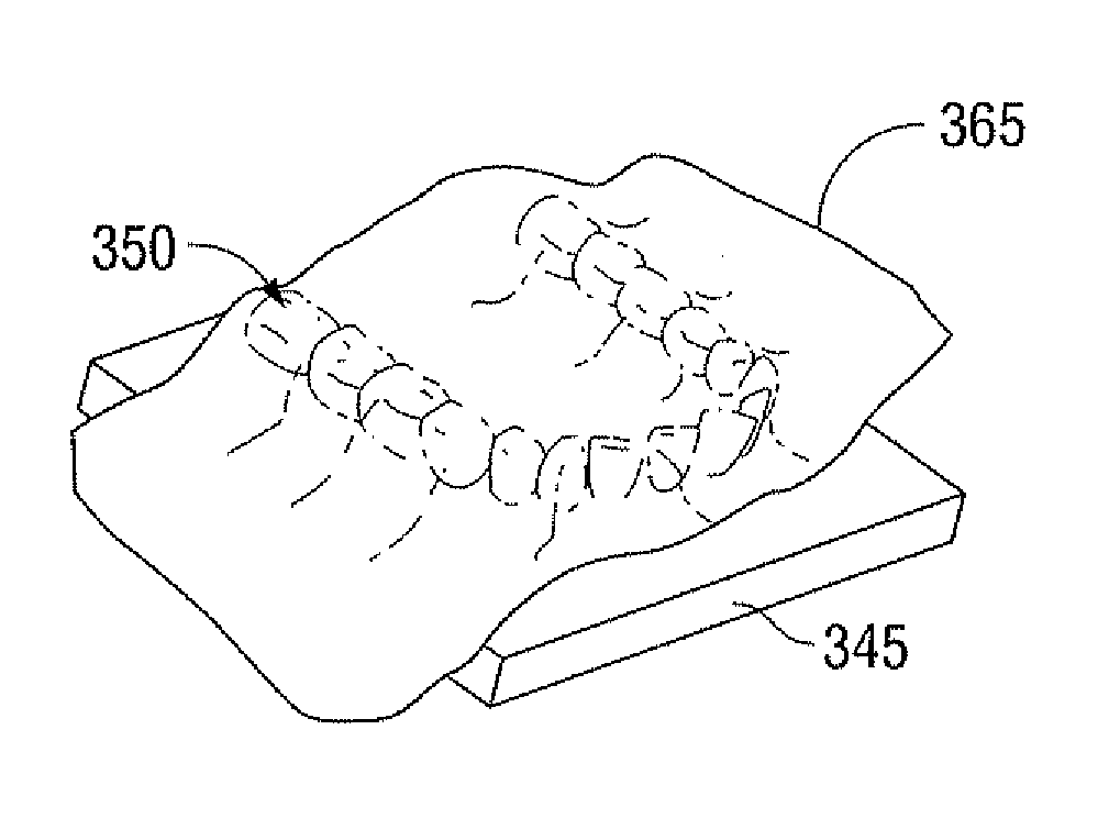
[0035]FIG. 5 shows a perspective view of a casting chamber that may be used to cast a dental arch in some variations.

[0036]FIG. 6 shows a base plate for...


PUM


Abstract

Methods and apparatus for visualizing and manipulating three-dimensional digital dental models and related methods and apparatus for dental treatments are disclosed. In one aspect, a method for visualizing and manipulating a three-dimensional digital dental model may comprise viewing the three-dimensional digital dental model and using hand gestures to instruct a computer to manipulate one or more teeth in the digital dental model. In other aspects, a dental treatment method may comprise viewing a three-dimensional digital model, using hand gestures, a conventional keyboard, and/or a conventional mouse to instruct a computer to manipulate one or more teeth in the digital model to generate a three-dimensional digital model of a modified arrangement of the subject's teeth, and fabricating one or more dental aligners configured to reposition the subject's teeth into the modified arrangement. Viewing may comprise stereoscopically viewing a digital dental model.

Description

CROSS-REFERENCE TO RELATED APPLICATIONS[0001]The present application claims the benefit of U.S. Provisional Application Ser. No. 60 / 798,237, filed May 5, 2006, which is incorporated herein by reference in its entirety.TECHNICAL FIELD[0002]This application generally relates to the field of dental care, and more particularly to the field of orthodontics.BACKGROUND[0003]Orthodontics is the practice of manipulating a subject's teeth to provide better function and appearance. Typically, brackets are bonded to a subject's teeth and coupled together with an arched wire. The combination of the brackets and wire provide a force on the teeth causing them to move. Once the teeth have moved to a desired location and are held in place for a certain period of time, the body adapts bone and the surrounding soft-tissue to maintain the teeth in the desired location. To further assist in retaining the teeth in the desired location, a subject may be fitted with a retainer.[0004]To achieve tooth moveme...

Claims


Application Information

Patent Timeline
Patent Type & Authority Applications(United States)
IPC IPC(8): A61C7/00G06T15/00G06F17/50G05B19/18
CPCA61C7/002A61C7/08G06T2219/2016G05B2219/45167G06T19/20G05B19/4097
Inventor WEN, HUAFENGCHISHTI, MUHAMMAD ZIAULLAH KHANBASHIR, YASSERASLAM, OMAIRATHAR, SOHAIB
Owner ALIGN TECH
Why Eureka
Try Eureka