Deposition chamber desiccation systems and methods of use thereof

a desiccation system and desiccation chamber technology, applied in drying machines, lighting and heating apparatus, furnaces, etc., can solve the problems of difficult removal of water, reduced thin film quality, and higher contamination levels

Inactive Publication Date: 2006-12-07
CARDINAL CG
View PDF18 Cites 23 Cited by
  • Summary
  • Abstract
  • Description
  • Claims
  • Application Information

AI Technical Summary

Benefits of technology

[0013] The present invention also includes a method for drying a deposition chamber that includes the steps of passing air through a desiccation system, blowing the dried air into a deposition chamber at or above atmospheric pressure, and withdrawing air from the deposition chamber after it has absorbed all or a portion of the moisture present within the chamber. Optionally, the air blown into the deposition chamber may be he

Problems solved by technology

Allowing the water to remain in the chamber is likely to reduce the quality of thin films produced.
Water is difficult to remove because of the strong bonding interaction between polar water molecules and the surfaces of the chamber and substrate.
Furthermore, hydrogen bonding between the water molecules themselves can cause the water to accumulate in layers, contributing to higher levels of contamination.
Additionally, water generally causes corrosion of sputtered films and glass surfaces.
Furthermore, water-related impurities are typically concentrated at the interface, and make it difficult to etch selectively or deposit a high quality film.
Also, water-related impurities impair adhesion and electric contact, add to the stress of the film, and generally result in a variety of film quality problems.
Undeposited water vapor within the chamber can cause additional problems in vapor deposition systems,

Method used


Image

  • Deposition chamber desiccation systems and methods of use thereof
  • Deposition chamber desiccation systems and methods of use thereof
  • Deposition chamber desiccation systems and methods of use thereof

Examples


Embodiment Construction

[0019] To better illustrate the invention, the preferred embodiments will now be described in more detail. Reference will be made to the drawings, which are summarized above. Reference numerals will be used to indicate parts and locations in the drawings. The same reference numerals will be used to indicate the same parts of locations throughout the drawing unless otherwise indicated.

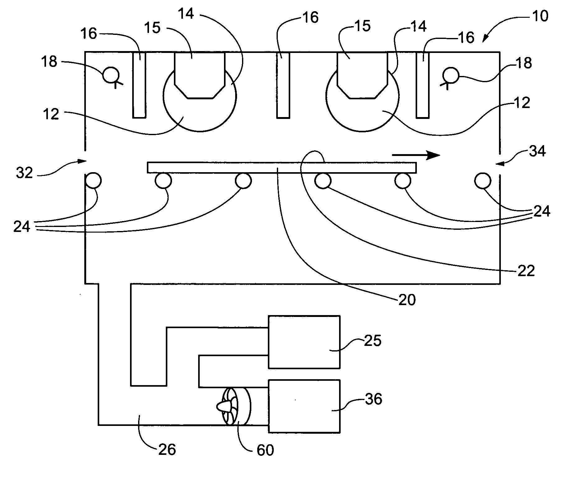
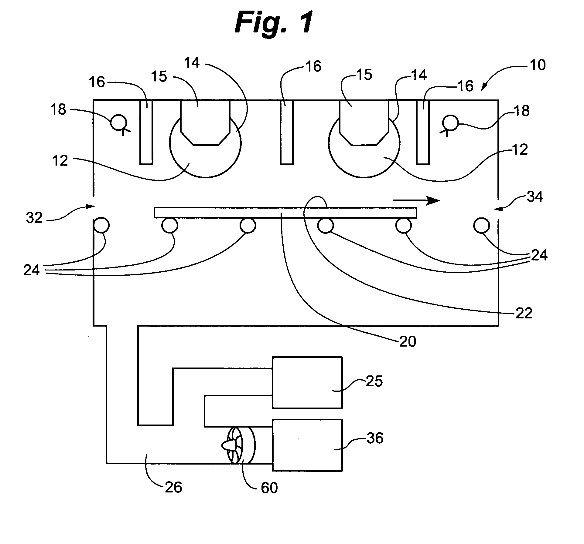
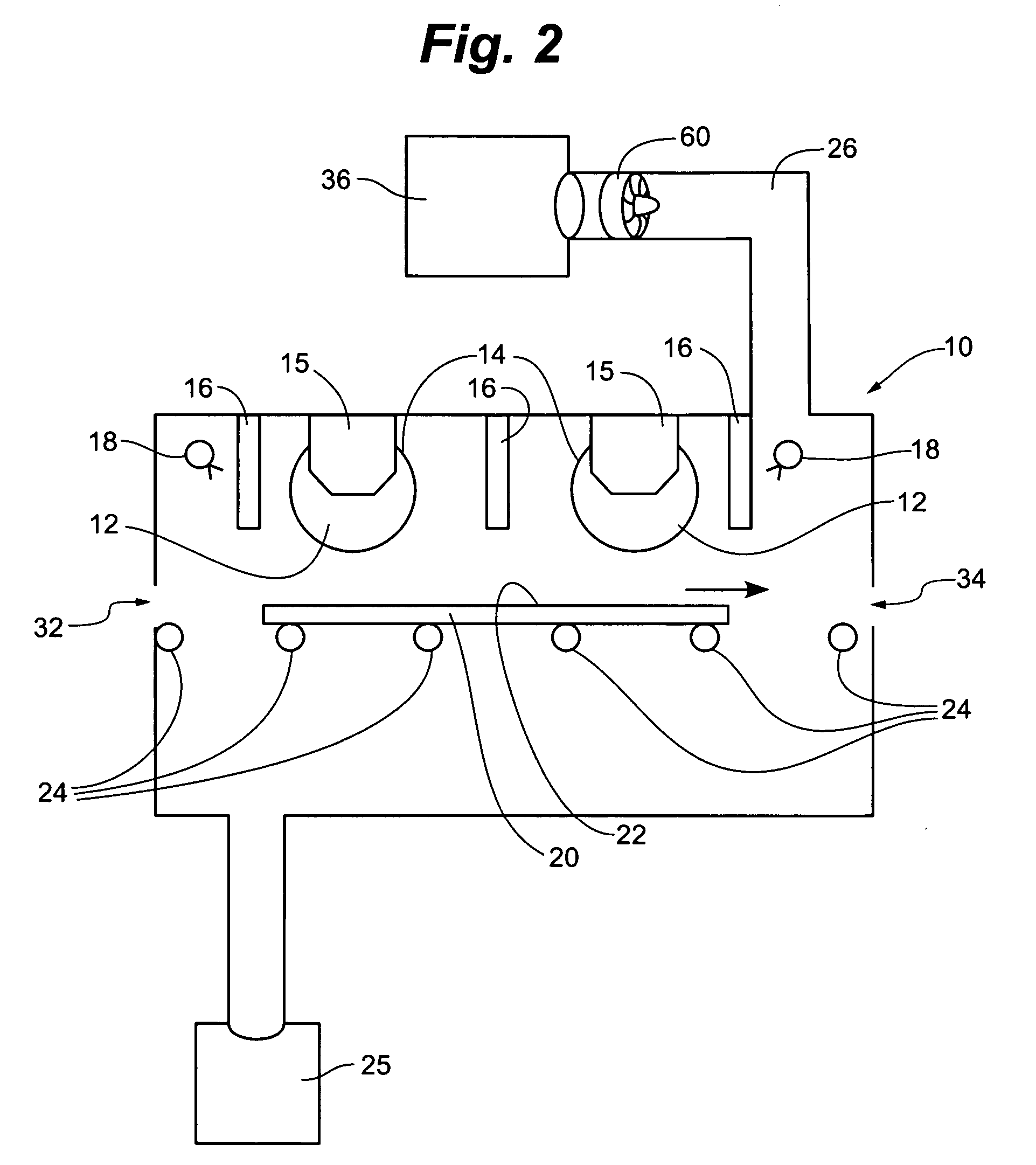
[0020] The present invention provides a system and method in which contaminating moisture within a deposition chamber is removed prior to use by flushing the deposition chamber with dry air. The deposition chamber is preferably part of a magnetron sputtering system. However, the described system and method of drying may also be used for non-magnetic sputtering deposition chambers. Dry air, preferably hot dry air, is delivered from a desiccation system through delivery lines at or above atmospheric pressure in order to flush the chamber of moisture. The deposition chamber and the drying apparatus used f...


PUM

PropertyMeasurementUnit
Temperatureaaaaaaaaaa

Abstract

The present invention provides a system and method for removing contaminating moisture from a deposition chamber prior to use. Dry air, preferably hot dry air, is blown into the deposition chamber where it absorbs and removes moisture. This is done by connecting a desiccation system including a blower and a dryer to the deposition chamber. The deposition chamber is also provided with a vacuum source; this may be connected to the deposition chamber using the same line as that used for the desiccation source, or may be connected through a separate line. The dry air may re-circulate through the chamber during this flushing method, or the dry air may flow through the deposition chamber continuously. A heat exchanger may also be provided to efficiently reuse hot air used to recharge the desiccation system. The desiccation system and method are particularly suited for decontaminating a magnetron sputtering deposition chamber.

Description

RELATED APPLICATION [0001] The present application claims priority to U.S. provisional patent application 60 / 682,986, filed May 20, 2005, the entire disclosure of which is incorporated herein by reference.FIELD OF THE INVENTION [0002] The present invention is related to a system and methods for drying a deposition chamber by flushing it with desiccated air. In various embodiments of the present invention, the desiccated air may also be heated to enhance the drying of the chamber. In particular, these systems and methods are useful for rapidly decontaminating and / or drying a magnetron sputtering deposition chamber prior to evacuation for thin film deposition. BACKGROUND OF THE INVENTION [0003] The present invention relates to systems and methods for desiccating deposition chambers that are used to run processes sensitive to the presence of moisture. Chemical and physical deposition processes such as chemical vapor deposition, plasma enhanced chemical vapor deposition, magnetron sputt...

Claims


Application Information

Patent Timeline
IPC IPC(8): F26B21/08
CPCC23C14/564F26B21/08F26B21/001C23C16/4401
Inventor HARTIG, KLAUS
Owner CARDINAL CG
Why Eureka
Try Eureka