Goal height adjuster lock

a height adjustment and lock technology, applied in the field of basketball goals, can solve the problems of unsatisfactory need, difficult to sustain upward force, loss of locking function of locking bolts, etc., and achieve the effect of sufficient mass

Active Publication Date: 2010-01-14
GARED HLDG
View PDF11 Cites 3 Cited by
  • Summary
  • Abstract
  • Description
  • Claims
  • Application Information

AI Technical Summary

Benefits of technology

[0008]In another aspect, the drive coupling can have a portion that can be coupled to a torque input device so that a torque applied to the drive coupling can cause rotation of the drive screw to vertically adjust the position of the backboard. The torque input device can have sufficient mass such that the weight of the torque input device can at least assist in overcoming the bias provided by the spring coupled between the drive coupling and the drive screw.

Problems solved by technology

Through use the C-shaped handles can become deformed or even break so that the locking function of the locking bolts can be lost.
While the application of the necessary upward force for sufficient time to make a minor adjustment in backboard position is not difficult, some people have found this upward force requirement to be difficult to sustain during the entire length of time sufficient to completely raise or lower the backboard assembly.
There is therefore an unsatisfied need for a backboard assembly that is vertically adjustable having a lock structure that automatically is engaged when the assembly is not being adjusted, yet can easily be unlocked when necessary by the application of only a minor amount of force.

Method used


Image

  • Goal height adjuster lock
  • Goal height adjuster lock
  • Goal height adjuster lock

Examples


Embodiment Construction

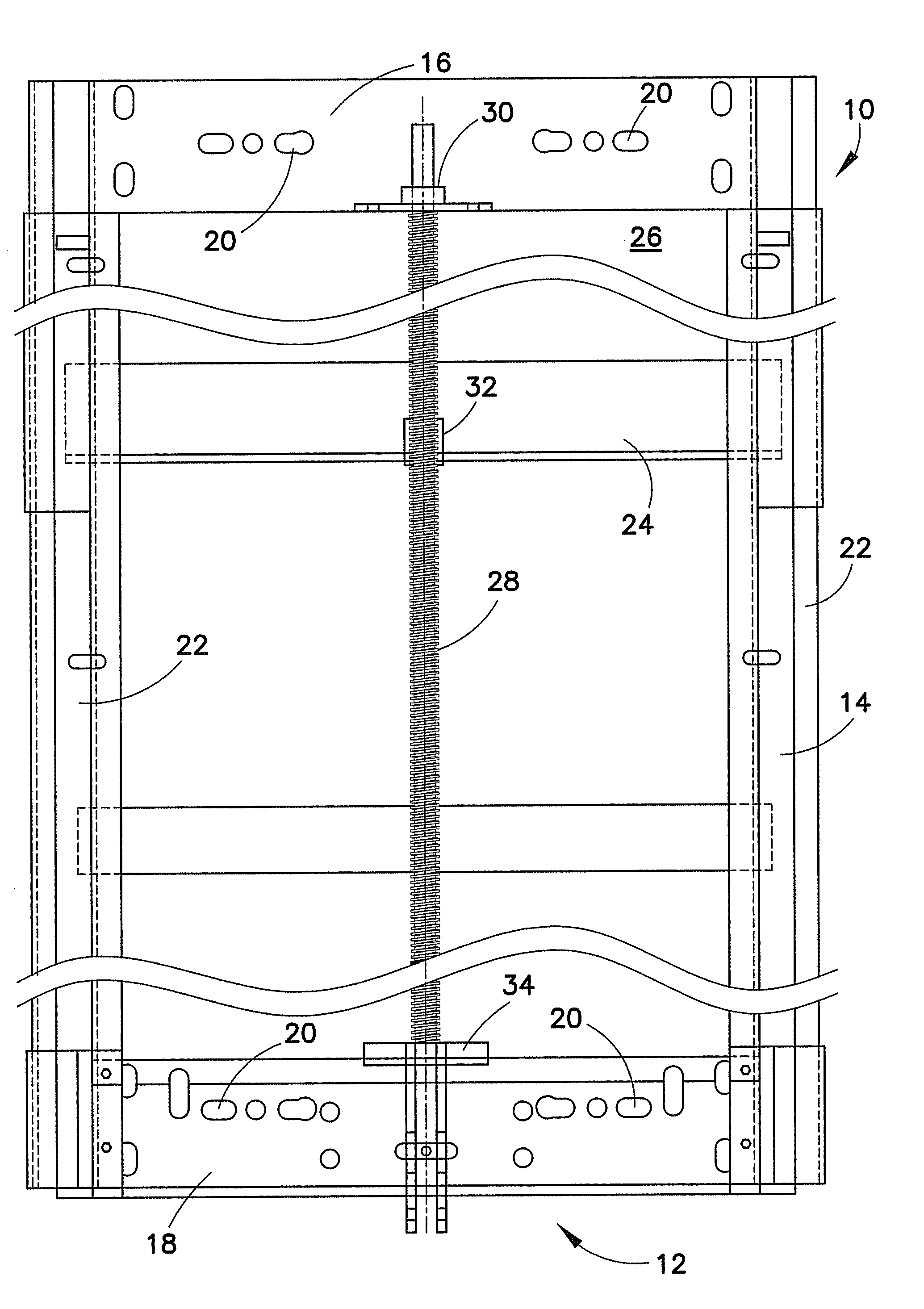
[0019]FIG. 1 is a back elevation view of an adjustable basketball backboard assembly 10 including a goal height adjuster lock 12 of the present invention. The adjustable basketball backboard assembly 10 can include a fixed support member 14 that is generally adapted to be fixed to a further support, not shown, which can be a suspended from a gymnasium ceiling, coupled to a gymnasium wall, or supported on a gymnasium floor or playground. The fixed support member 14 can include an upper horizontal member 16 and a lower horizontal member 18. The members 16 and 18 can include suitable openings 20 for receiving coupling members, such as bolts, screws, or the like, not shown, for coupling the support member 14 to the further supports described above. The fixed support member 14 can also include one or more vertical members 22 fixed to members 16 and 18 to provide a track, race, or pathway for a movable support member 24. A basketball backboard 26 can be coupled to the movable support memb...


PUM


Abstract

A fixed support member includes upper and lower horizontal plates, and a movable support member is coupled to the fixed support member for vertical movement. A drive screw extending between the fixed support member upper and lower horizontal plates and coupled to the movable support member for adjusting the position of the movable support member relative to the fixed support member by rotation of the drive screw. A locking plate fixed to a lower surface of the fixed support member lower horizontal plate having an opening receiving a lower end of the drive screw. A drive coupling connected to the lower end of the drive screw has a portion that can be coupled to a torque input device so that a torque applied to the drive coupling can cause rotation of the drive screw. The drive coupling has an upper portion shaped to be received in the locking plate opening to prevent rotation of the drive coupling and drive screw. A spring coupled between the drive coupling and the drive screw biases the drive coupling toward engagement with the locking plate opening.

Description

BACKGROUND OF THE INVENTION[0001]1. Field of the Invention[0002]The present invention generally relates to basketball goals that are vertically adjustable in position, and to a lock for locking the goal at any selected vertical height. The present invention more particularly relates to such goals that are vertically adjustable in position by means of a threaded drive screw and a lock for preventing any undesired rotation of the drive screw.[0003]2. Description of the Prior Art[0004]Basketball goals that are present in multi-use gymnasiums are generally movable from a use position to a storage position so that activities other than basketball can proceed without the interference of the basketball goal. Even the use position of a given basketball goal can vary depending upon the age of the basketball game participants. Thus for many years, basketball goals have been vertically positioned by a variety of mechanisms. One such mechanism, shown in Chervenka U.S. Pat. No. 2,916,288, involv...

Claims


Application Information

Patent Timeline
Patent Type & Authority Applications(United States)
IPC IPC(8): A63B63/08
CPCA63B2225/093A63B63/083Y10T70/50
Inventor CONNERLEY, JAMES J.PERRY, JR., DAVID W.
Owner GARED HLDG
Why Eureka
Try Eureka