
Speed regulated pipeline pig

a technology of pipeline pigs and speed regulation, applied in the field of pipeline pigs, can solve the problems of requiring means for increasing the speed of pigs, not preventing pigs from stalling, and not preventing, so as to reduce the bypass flow and minimize the effect of the “bouncing” effect of the stopper

Active Publication Date: 2014-02-18
TDW DELAWARE INC
View PDF22 Cites 9 Cited by
  • Summary
  • Abstract
  • Description
  • Claims
  • Application Information

AI Technical Summary

Benefits of technology

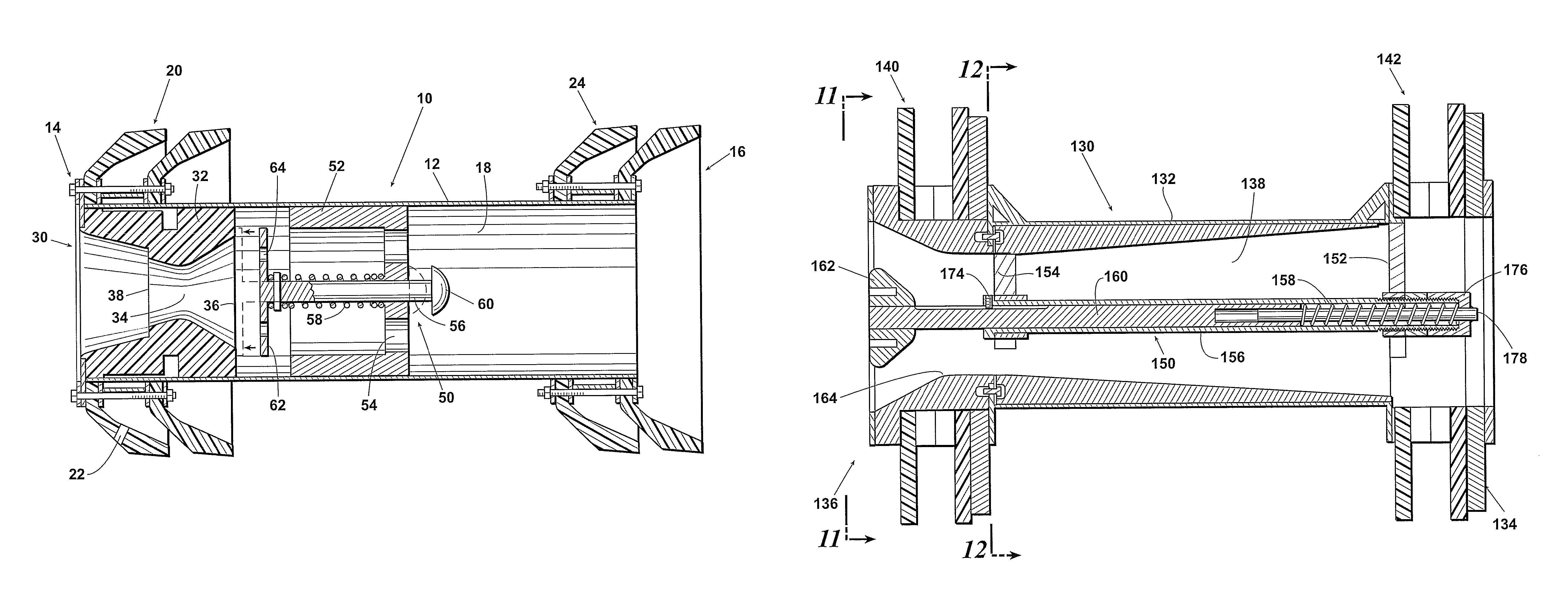
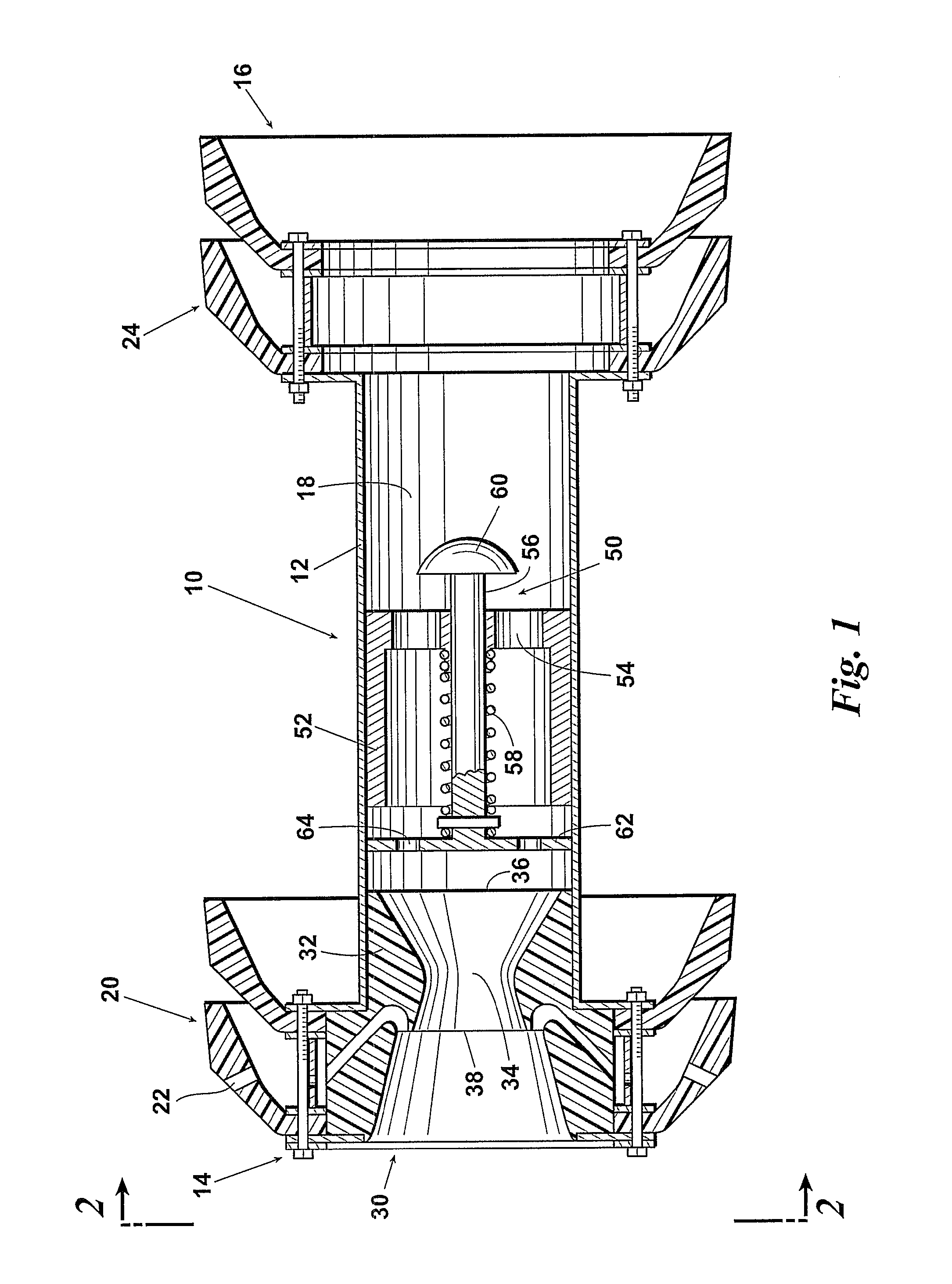
[0011]A pipeline pig made according to this invention has a longitudinal pig body with a forward end, a rearward end, a central passageway, and a plurality of external circumferential seating elements in sealing engagement with a pipeline. The central passageway includes a venturi preferably concentric to the pig body. The venturi may be provided by a nozzle affixed to the forward end of the pig. A modulating valve, which is also preferably concentric to the pig body, is located rearward of the inlet side of the venturi. The venturi, modulating valve, or both may be non-concentric to the pig body. The modulating valve has an open or withdrawn position and a closed (or partially closed) or extended position relative to the venturi. When the modulating valve is in the open position, a predetermined maximum bypass flow is allowed through the venturi. If this maximum bypass is exceeded due to the pig stalling, the valve substantially instantly moves to the closed position. The closed position allows a predetermined minimum bypass flow through the venturi in order to substantially immediately start the pig moving again before significant pressure builds up behind the pig. The valve then substantially instantly moves to the open position. This prevents the pig from surging to speeds higher than the average fluid flow.
[0013]The modulating valve may be a poppet-style valve having a compression or tension spring, a plate, and an insert. The plate and the insert each has a plurality of ports that allow bypass flow through the plate and insert, respectively. The face of the plate may be substantially flat or substantially the same shape as an interior surface of the venturi. When the valve is closing, the plate extends toward the inlet side of the venturi to reduce bypass flow to the minimum bypass flow.
[0014]The modulating valve may also be a frusto-conical shaped valve or stopper. The stopper has sufficient mass to overcome the spring force holding the modulating valve in its open position. When the pipeline pig stalls, the valve closes and the stopper chokes bypass flow through the venturi to the predetermined minimum bypass flow. The peripheral surface of the stopper preferably has substantially the same shape as the interior surface of the venturi. When the pig starts running again, the valve opens as inertia forces the stopper away from the inlet side of the venturi. The use of a mass damper device may also minimize any “bouncing” effect of the stopper.

Problems solved by technology

In addition, pipeline debris and build-up may slow the pig below a desired minimum speed, thereby requiring means for increasing pig speed.
The valve, however, does not prevent the pig from stalling, nor does it prevent speed surges above that of the pipeline fluid propelling the pig.
None of those control means, however, prevent the pig from stalling or controlling speed surges.
U.S. Pat. No. 2,860,356, however, requires the use of multiple valves in large pigs and in high velocity pipeline applications; therefore, it—along with the other prior alt devices—is not optimized for maximum speed reduction of the pig.
Additionally, none of the prior art devices prevent stalling or surging.
When the pig stalls, significant pressure may build up behind the pig and cause the pig to surge to speeds even higher than the average fluid flow through the pipeline.
This is problematic, for example, in dispersal-type pigs.
Although the dispersion method generally results in an improved coating application of the interior cylindrical wall of the pipeline, an inability to control the amount of bypass flow, and therefore control the maximum flow rate through the nozzle, erodes the effectiveness of the dispersion.
The high velocity of product passing through the nozzle may stall the pig, resulting in pressure buildup behind the pig that causes the pig's speed to surge far above the speed at which it effectively disperses the liquid.
A large amount of bypass may slow the pig and cause it to stall, especially as debris builds up in front of the pig.
This stalling may result in pressure build-up and surging (as described above), resulting in high pig velocity and skating over portions of the debris.

Method used


Image

  • Speed regulated pipeline pig
  • Speed regulated pipeline pig
  • Speed regulated pipeline pig

Examples


Embodiment Construction

[0030]Preferred embodiments of a speed regulated pipeline pig will now be described by making reference to the drawings and the following elements illustrated in the drawings:

[0031]

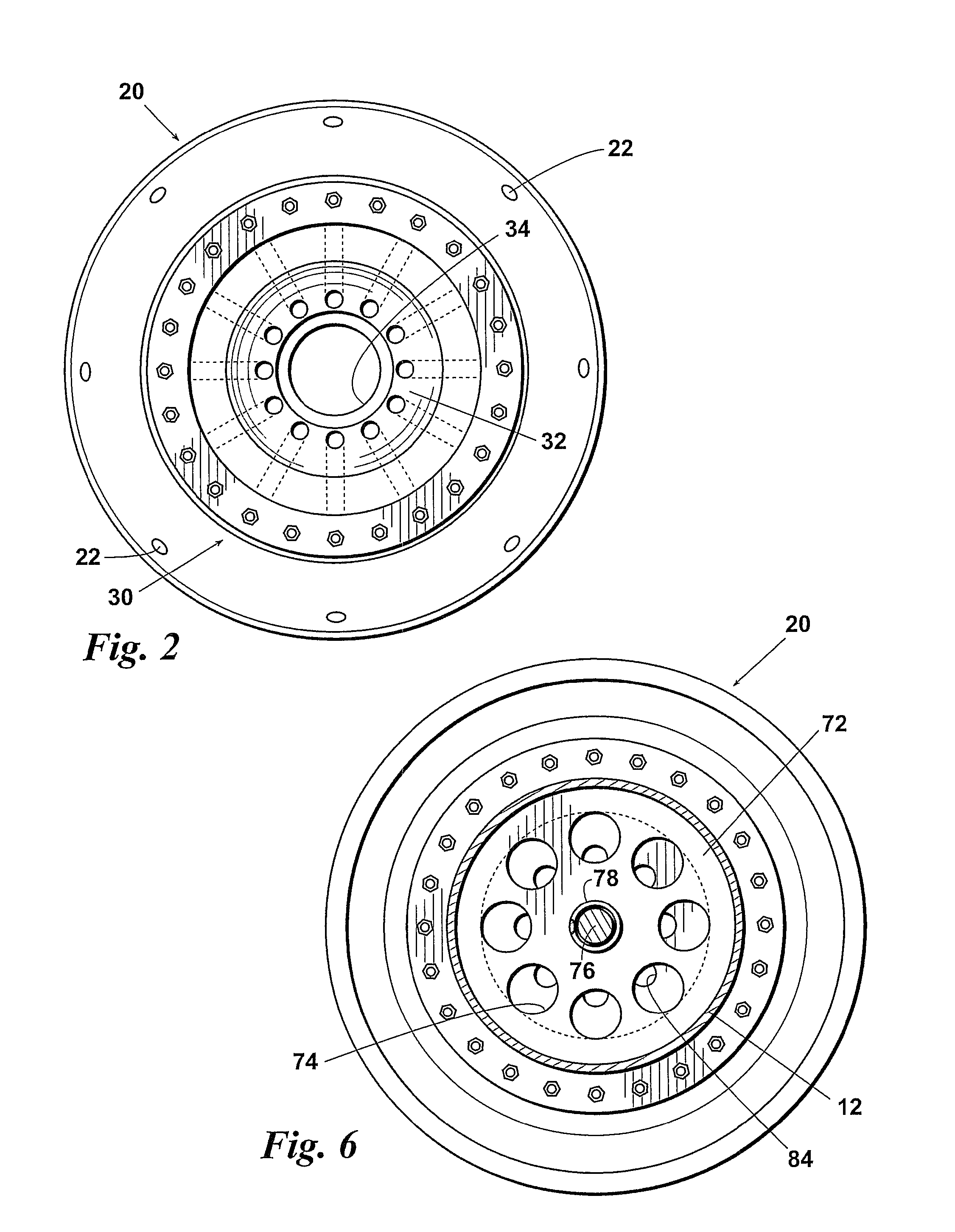
10Pipeline pig12Body14Forward end16Rearward end18Passageway20Forward sealing cups22Perforation24Rearward sealing cups30Nozzle32Insert34Venturi36Inlet side38Discharge side40Interior surface50Modulating valve52Insert54Port56Plunger58Tension spring60Head62Plate64Port70Modulating valve72Insert74Port76Plunger78Compression spring80Head82Plate84Port86Angular surface88Arcuate surface130Pipeline pig132Body134Forward end136Rearward end138Passageway140Rearward sealing discs142Forward sealing discs150Modulating valve152Bracket154Bracket156Housing158Spring160Plunger162Valve head164Venturi166Inlet side168Split collar170Pin172Bolt174Set screw176Capture nut178Bolt

[0032]Referring to the drawings, and first to FIGS. 1 to 3, a pipeline pig 10 having a longitudinal, cylindrical body 12 has a forward end 14, a rearward end 16...


PUM


Abstract

A pipeline pig includes a venturi and a modulating valve located rearward of the inlet side of the venturi. When the valve is in the open position, a predetermined maximum bypass flow is allowed through the venturi. The closed position allows a predetermined minimum bypass flow. The valve may be a poppet-style valve or a frusto-conical shaped stopper. The stopper has sufficient mass and / or aerodynamic drag to overcome the spring force holding the valve in the open position. When the pig stalls, the valve closes and the stopper chokes bypass flow through the venturi. When the pig starts running again, the valve opens as inertia forces the stopper away from the inlet side of the venturi. Also, as friction of the pig increases due to changes in the internal diameter of the pipeline or accumulation of debris ahead of the pig, increased airflow across the valve creates drag sufficient to partially overcome the spring force, thus keeping the pig moving at a desirable rate of travel.

Description

REFERENCE TO PENDING APPLICATIONS[0001]This application is not based upon any pending domestic or international patent applications.FIELD OF THE INVENTION[0002]This invention relates generally to a pipeline pig that services a pipeline and moves through the interior of the pipeline by the flow of pressurized gas. More specifically, this invention relates to regulating the speed of the pipeline pig and preventing its stalling in high velocity pipelines.BACKGROUND OF THE INVENTION[0003]Pipeline pigs for inspecting, servicing, and maintaining pipelines are typically moved along the interior of the pipeline under pressure. Absent any speed control, the pig travels at essentially the same rate of speed as the pipeline fluid propelling it. In many cases, the speed of the pipeline fluid exceeds the desired range in which the pig is most effective for its intended use. In addition, pipeline debris and build-up may slow the pig below a desired minimum speed, thereby requiring means for incre...

Claims


Application Information

Patent Timeline
Patent Type & Authority Patents(United States)
IPC IPC(8): B08B9/04
CPCB08B9/0557F16L55/38
Inventor PRUETT, RICK D.STRONG, ROBERT F.FREEMAN, ERIC N.COOPER, CHARLES CULVER GIDDENNELSON, SCOTT DOUGLASHENAULT, MARK RUSSELL
Owner TDW DELAWARE INC
Learn More