Internal combustion engine with turbocharger surge detection and control

a turbocharger and internal combustion engine technology, applied in the direction of engine starters, machines/engines, instruments, etc., can solve the problems of reducing the maximum combustion temperature within the cylinder, affecting the discharge process, and unable to increase the flow rate further

Active Publication Date: 2009-09-10
DEERE & CO
View PDF20 Cites 18 Cited by
  • Summary
  • Abstract
  • Description
  • Claims
  • Application Information

AI Technical Summary

Benefits of technology

[0007]The invention in one form is directed to an internal combustion engine, including a block defining a plurality of combustion cylinders, an intake manifold fluidly coupled with at least one combustion cylinder, and an exhaust manifold fluidly coupled with at least one combustion cylinder. A turbocharger includes a turbine fluidly coupled with the exhaust manifold, and a compressor fluidly coupled with the intake manifold. The compressor includes an inlet and an outlet. A microphone is positioned in association with the compressor inlet or the compressor outlet. The microphone provides an output signal. An engine control unit (ECU) coupled with the microphone controls operation of the turbocharger to prevent surge of the compressor, dependent upon the output signal from the microphone.
[0008]The invention in another form is directed to an internal combustion engine including a block defining a plurality of combustion cylinders, an intake manifold fluidly coupled with at least one combustion cylinder, and an exhaust manifold fluidly coupled with at least one combustion cylinder. A turbocharger includes a variable geometry turbine (VGT) which is fluidly coupled with the exhaust manifold, and a compressor which is fluidly coupled with the intake manifold. The compressor includes an inlet and an outlet. A microphone positioned in association with the compressor inlet or the compressor outlet provides an output signal. An ECU coupled with the microphone controls operation of the VGT to prevent surge of the compressor, dependent upon the output signal from the microphone.

Problems solved by technology

With too small a volume flow and too high a pressure ratio, the flow will separate from the suction side of the blades on the compressor wheel, with the result that the discharge process is interrupted.
When the flow rate at the compressor inlet or other location reaches sonic velocity, no further flow rate increase is possible and choking results.
The exhaust gas which is reintroduced to the engine cylinder reduces the concentration of oxygen therein, which in turn lowers the maximum combustion temperature within the cylinder and slows the chemical reaction of the combustion process, decreasing the formation of nitrous oxides (NOx).
Furthermore, the exhaust gases typically contain unburned hydrocarbons which are burned on reintroduction into the engine cylinder, which further reduces the emission of exhaust gas by-products which would be emitted as undesirable pollutants from the IC engine.
When the exhaust manifold pressure is higher than the intake manifold pressure and the EGR valve is open, some of the intake gases to the intake manifold are drawn from the exhaust manifold, which in turn reduces the volumetric flow rate from the turbocharger compressor.
Thus, the problem of compressor surge is compounded with the use of EGR.

Method used


Image

  • Internal combustion engine with turbocharger surge detection and control
  • Internal combustion engine with turbocharger surge detection and control
  • Internal combustion engine with turbocharger surge detection and control

Examples


Embodiment Construction

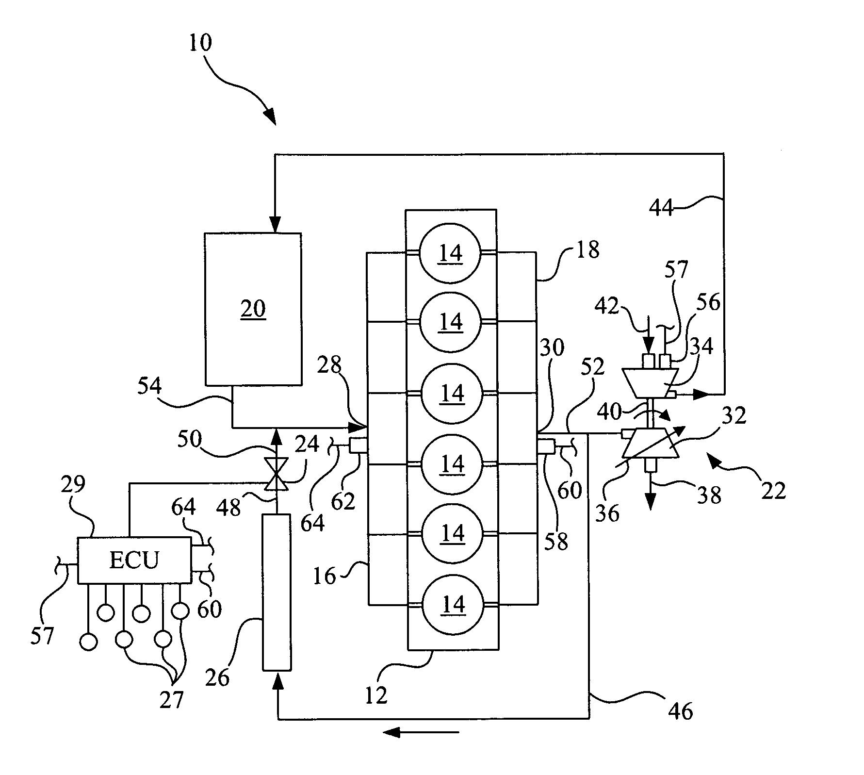
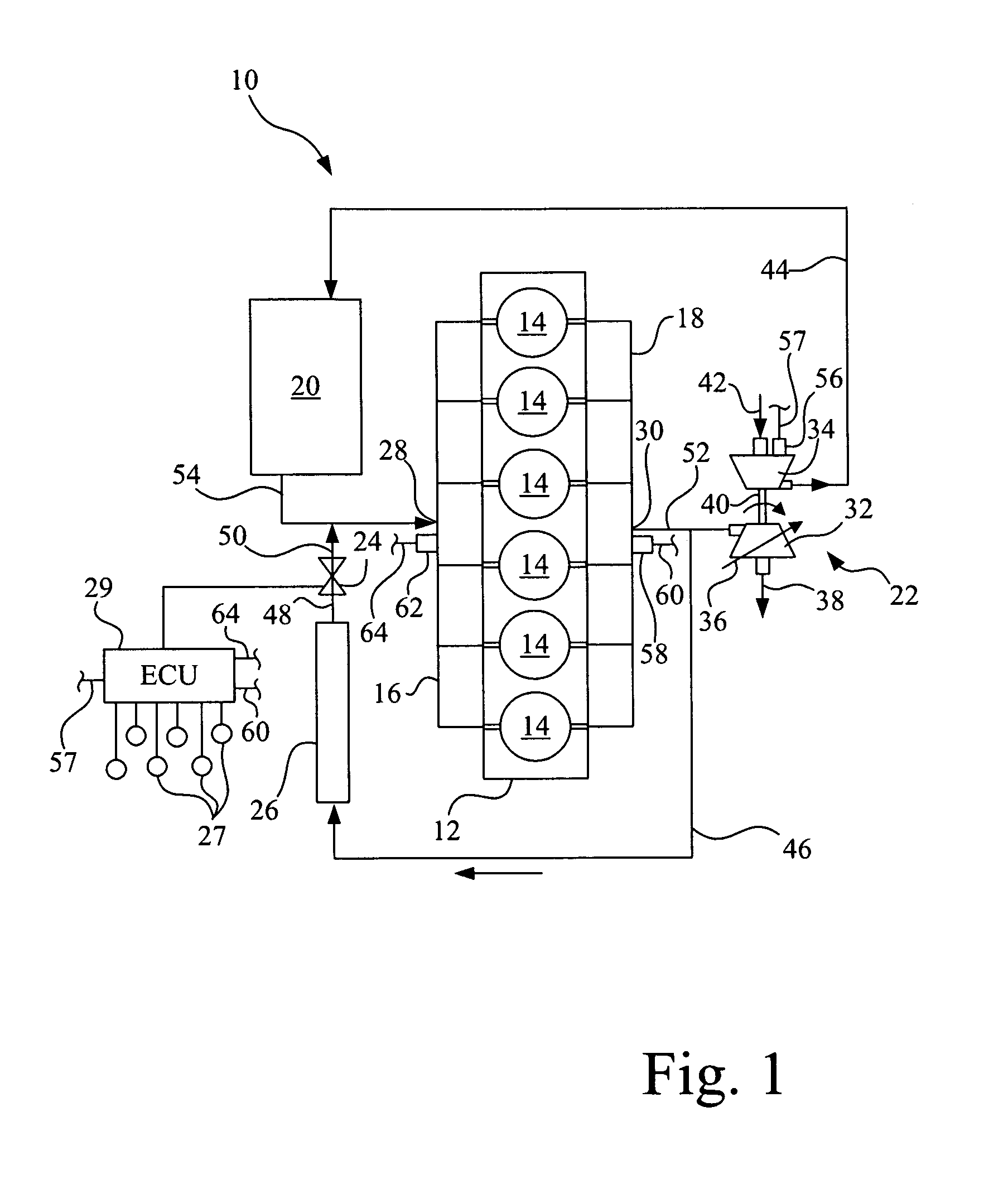
[0011]Referring now to the drawings, and more particularly to FIG. 1, there is shown an embodiment of an IC engine 10 of the present invention, which generally includes a block 12 having a plurality of combustion cylinders 14, intake manifold 16, exhaust manifold 18, charge air cooler 20, turbocharger 22, EGR valve 24 and EGR cooler 26. In the embodiment shown, IC engine 10 is a diesel engine which is incorporated into a work machine, such as an agricultural tractor or combine, but may be differently configured, depending upon the application.

[0012]Block 12 is typically a cast metal block which is formed to define combustion cylinders 14. In the embodiment shown, block 12 includes six combustion cylinders 14, but may include a different number depending upon the application. Intake manifold 16 and exhaust manifold 18 are also typically formed from cast metal, and are coupled with block 12 in conventional manner, such as by using bolts and gaskets. Intake manifold 16 and exhaust mani...


PUM


Abstract

An internal combustion engine includes a block defining a plurality of combustion cylinders, an intake manifold fluidly coupled with at least one combustion cylinder, and an exhaust manifold fluidly coupled with at least one combustion cylinder. An EGR valve may be fluidly coupled between the exhaust manifold and the intake manifold. A turbocharger includes a turbine fluidly coupled with the exhaust manifold, and a compressor fluidly coupled with the intake manifold. A microphone is positioned at the compressor inlet or the compressor outlet provides an output signal. An ECU is coupled with the microphone, and controls operation of an actuatable element of a VGT, an EGR valve, and/or an injected fuel quantity, to prevent surge of the compressor, dependent upon the output signal from the microphone.

Description

FIELD OF THE INVENTION[0001]The present invention relates to internal combustion engines, and, more particularly, to turbochargers and turbocharger systems used with such engines.BACKGROUND OF THE INVENTION[0002]An internal combustion (IC) engine may include one or more turbochargers for compressing a fluid which is supplied to one or more combustion chambers within corresponding combustion cylinders. Each turbocharger typically includes a turbine driven by exhaust gases of the engine and a compressor which is driven by the turbine. The compressor receives the fluid to be compressed and supplies the fluid to the combustion chambers. The fluid which is compressed by the compressor may be in the form of combustion air or a fuel and air mixture.[0003]The operating behavior of a compressor within a turbocharger may be graphically illustrated by a “compressor map” associated with the turbocharger in which the pressure ratio (compression outlet pressure divided by the inlet pressure) is p...

Claims


Application Information

Patent Timeline
Patent Type & Authority Applications(United States)
IPC IPC(8): F02D23/00G06F17/00F02B33/44
CPCF02B2039/168F02B39/16
Inventor WINSOR, RICHARD E.MCMULLEN, ROBERT J.
Owner DEERE & CO
Why Eureka
Try Eureka