Vertical axis wind turbine and generator

a technology of wind turbine and generator, applied in the direction of motors, dynamo-electric machines, electrical equipment, etc., can solve the problem of significant addition of towers to the cost of installation

Inactive Publication Date: 2010-01-21
JESSIE DARRYL
View PDF15 Cites 40 Cited by
  • Summary
  • Abstract
  • Description
  • Claims
  • Application Information

AI Technical Summary

Problems solved by technology

The tower adds significantly t

Method used


Image

  • Vertical axis wind turbine and generator
  • Vertical axis wind turbine and generator
  • Vertical axis wind turbine and generator

Examples


Embodiment Construction

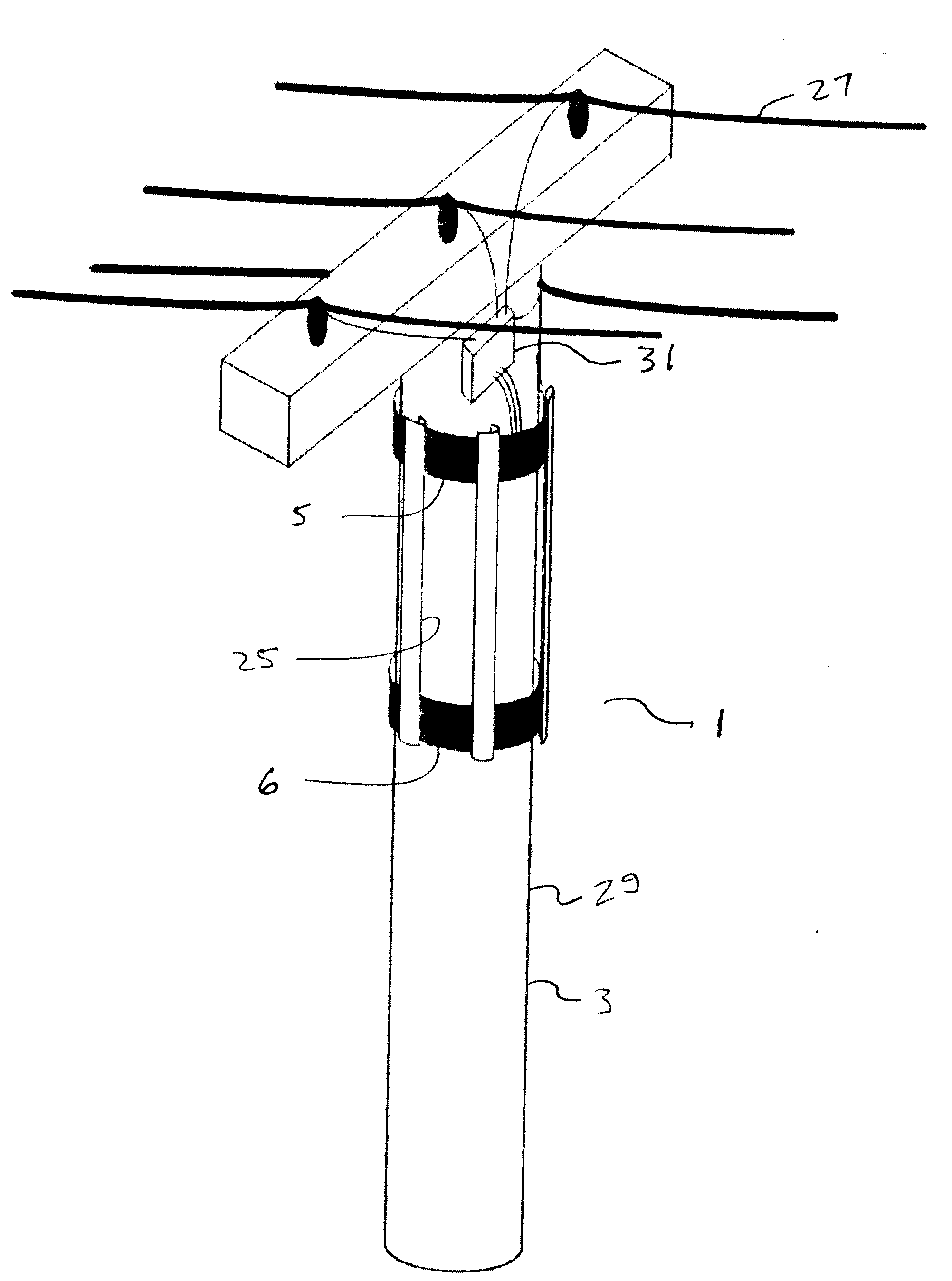
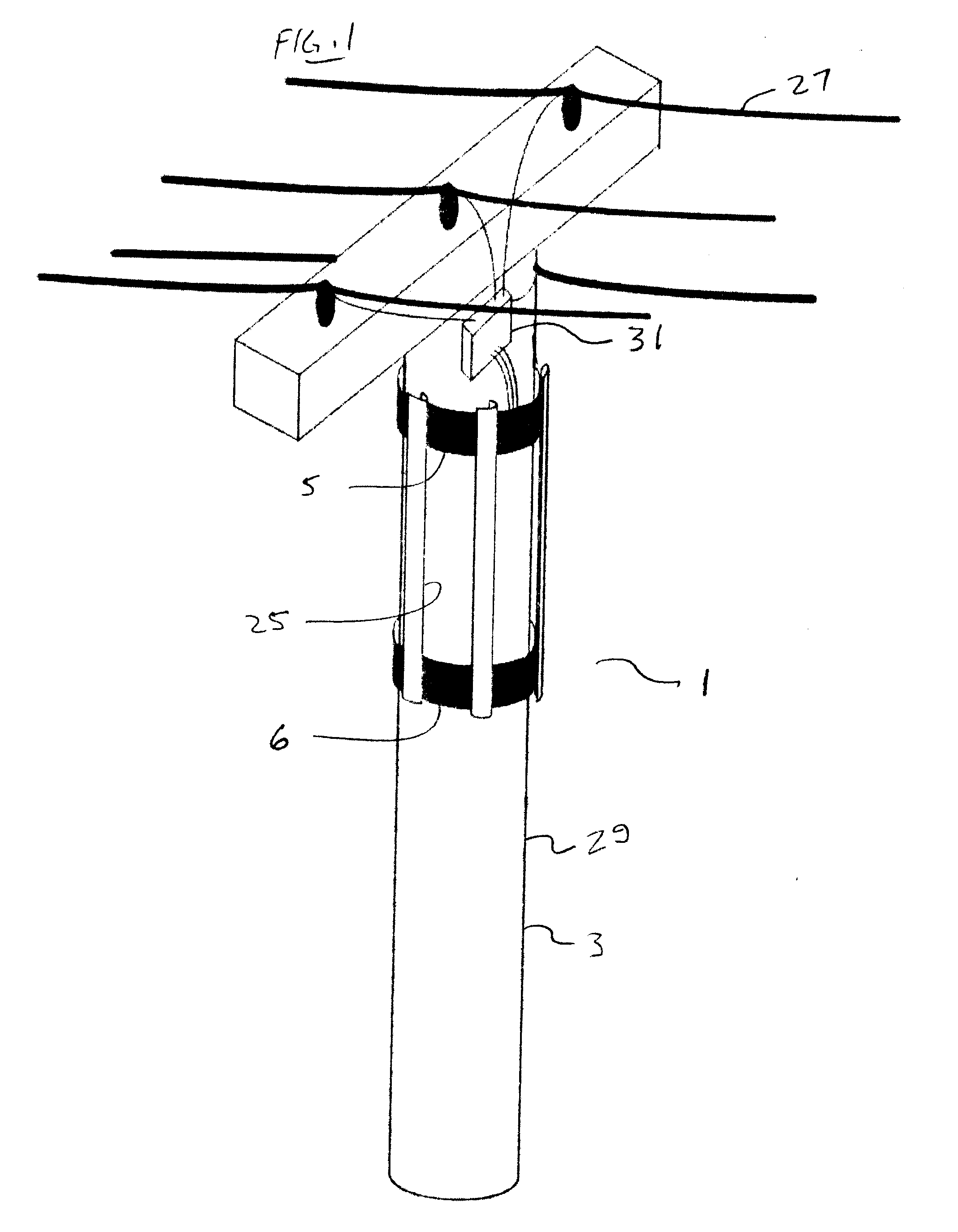
[0022]FIG. 1 illustrates a schematic view of an embodiment of a wind turbine and generator apparatus 1 of the present invention, mounted on a substantially vertical fixed cylindrical object 3, illustrated as an electrical utility pole, but which could also be a chimney, pipe, pole, or the like. The illustrated apparatus includes a generator 5, and a bearing 6.

[0023]The generator 5 comprises, as is well known in the art, a stationary generator member and a rotating generator member that encloses the stationary member, and the members are configured such that the as the rotating generator member rotates about the stationary generator member, an electrical current is generated. In the simplest embodiment the stationary member of the generator defines a central aperture sized to accommodate the cylindrical object 3, and the stationary member is installed on the cylindrical object 3 by inserting an end of the cylindrical object 3 through the aperture and moving the stationary generator m...


PUM


Abstract

A wind turbine and generator apparatus for mounting on a substantially vertical fixed cylindrical object includes a stationary generator member encircling the cylindrical object and fixed to the cylindrical object. A rotating generator member encloses the stationary generator member, and is rotatably supported by the stationary generator member. A plurality of blades is mounted to the rotating generator member such that a wind contacting the blades is operative to rotate the rotating generator member about the stationary generator member to generate electrical energy.

Description

[0001]This invention is in the field of wind energy and in particular a vertical axis wind turbine and generator for mounting on a substantially vertical cylindrical object.BACKGROUND[0002]Wind turbines generally are configured either as a horizontal axis wind turbine (HAWT) where the rotational axis is substantially aligned with the wind direction, or as a vertical axis wind turbine (VAWT) where the rotational axis is substantially vertical and perpendicular to the wind direction. The HAWT typically must be mounted so as to pivot about a vertical axis to align itself with the wind direction, while a VAWT generally can be fixed, since it will be rotated by the wind regardless of the wind direction. Thus the VAWT is somewhat less complex, and provides improved operation where winds are turbulent, such as in urban areas where buildings affect wind flow.[0003]Wind turbines are typically mounted on towers that position the turbines a significant distance above the ground where wind spee...

Claims


Application Information

Patent Timeline
IPC IPC(8): F03D3/06F03D3/02F03D11/02F03D11/04F03D9/34F03D13/20F03D15/00
CPCF03D3/007F03D3/061Y02E10/74H02K7/183F03D3/065F03D3/062
Inventor JESSIE, DARRYLCOTE, DAVE A.
Owner JESSIE DARRYL
Why Eureka
Try Eureka