Systems for Controlling Computers and Devices

a computer and computer technology, applied in computing, instruments, electric digital data processing, etc., can solve the problems of clogging the operating environment, reducing control and speed, and prolonging the procedure time, so as to achieve the effect of reducing input errors

Inactive Publication Date: 2010-01-21
MAESTRO MEDICAL SYST
View PDF33 Cites 65 Cited by
  • Summary
  • Abstract
  • Description
  • Claims
  • Application Information

AI Technical Summary

Benefits of technology

[0005]Optical computer input devices should provide robust, reliable computer input signals. It is important to minimize input errors due to light from other reflectors or light sources as well as from misinterpretation of the desired input from the actual optical computer input device. It is also desirable to be able use the computer input device with more than one computer or computer-based device and for the device to be able to perform multiple different kinds of computer input operations.

Problems solved by technology

These methods suffer from diminished control and speed and can clutter the operating environment.
Leaving the sterile filed and / or “unscrubbing” lengthens the time of the procedure and potentially puts the patient at a greater risk.
This may also cost the medical practitioner and hospital / clinic added time and increases the use of materials.
Furthermore, it may compromise the overall sterility of the procedure.
Other prior art devices use multiple retroreflectors, but do so in a way that is prone to misuse by the user or misinterpretation by the computer.
Some prior art systems are unnecessarily complex, requiring, e.g., use of a focusing lens with the photodetector.

Method used


Image

  • Systems for Controlling Computers and Devices
  • Systems for Controlling Computers and Devices
  • Systems for Controlling Computers and Devices

Examples


third embodiment

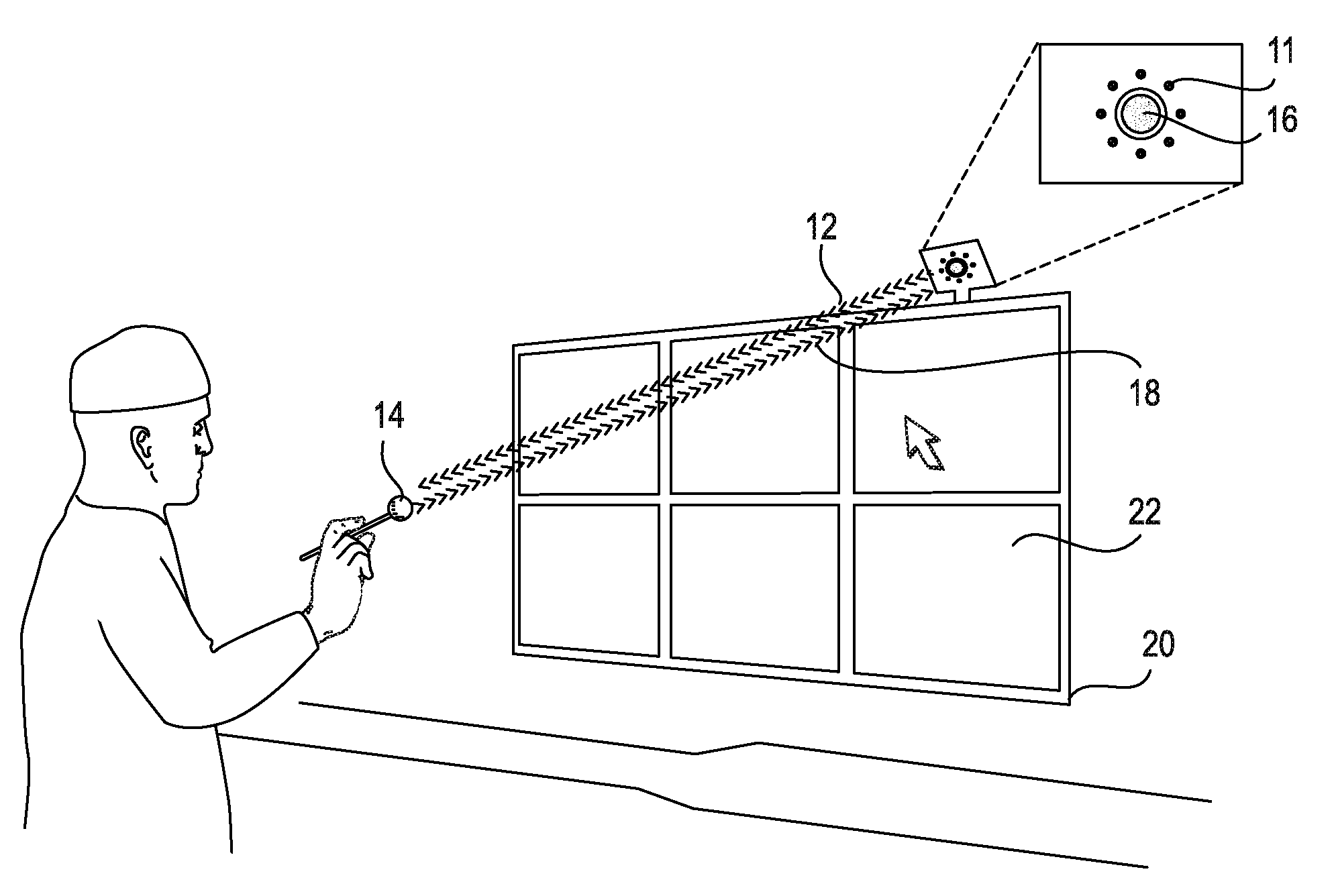
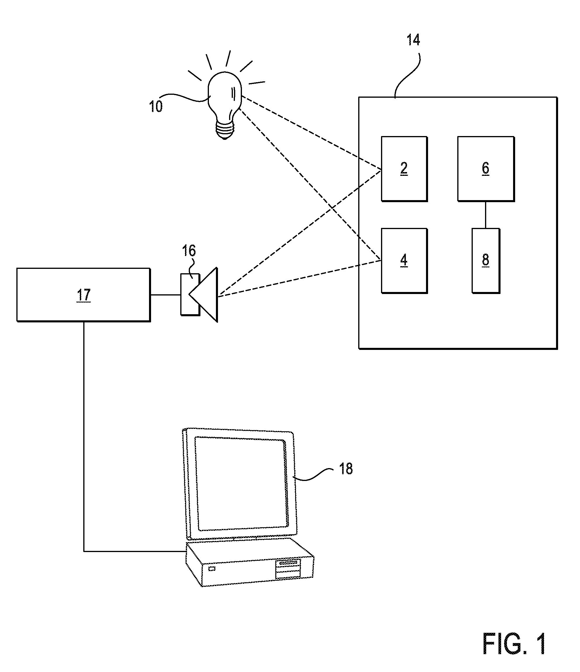
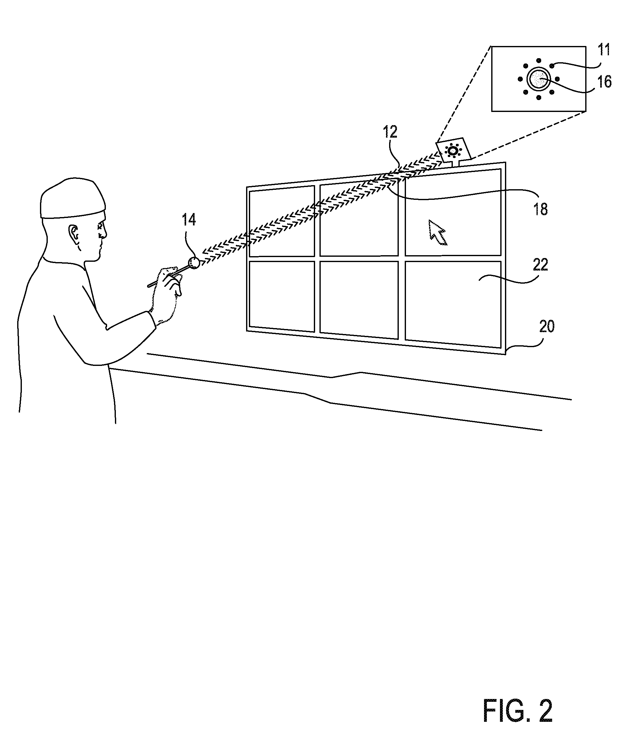
[0159]In a third embodiment, the first and second detectors may allow for the three dimensional (3D) spatial position of the reflective elements to be determined. In some embodiments, the 3D spatial information of the reflective elements can be used to control surgical instruments, for example, in 3D. For example, an instrument could me controlled by the system such that is can be moved back and forth (i.e., toward and away from the detector, for example) in addition to up / down / left / right. This may allow for more degrees of control and more flexibility in how instruments can be manipulated. Alternatively, the different dimensions of movement may be tied to separate inputs or actions. For example, movement in the x-axis may perform an input related to the brightness of the lights, movement in the y-axis may perform an input related to the height of the light from the table, and movement in the z-axis may perform an input related to a camera. In some embodiments, the system may furthe...

first embodiment

[0160]In some embodiments, the change detected by the system from the first pattern to the second pattern of reflected light further performs at least one of changing an image on the viewing screen, selecting an item on the viewing screen, selecting and dragging an item across the viewing screen, changing function of a cursor, initiating drawing on the viewing screen, stopping drawing on the viewing screen, and measuring a distance on the screen. Particularly, the system may provide the user with the ability to draw or make diagrams on the screen. For example, if a surgeon wanted to lay out where to make an incision and / or point out structures to avoid. In a first embodiment, a user may activate a foot pedal to initiate drawing on the screen. For example the movement of at least one of the reflective elements on the interface or coupled to the user (the movement of the body of the interface) is translated to the movement of a cursor on the screen. Upon activation of the foot pedal (...


PUM


Abstract

One aspect of the invention provides computer input system including a registered light source that emits light and an interface including first and second reflective elements configured to reflect light emitted by the registered light source, a body, and a movable member coupled to the body. A portion of the movable member is movable with respect to the body to change the light reflected from the first and second reflective elements from at least a first pattern to a second pattern. The system includes a detector configured to detect light reflected by the first and second reflective elements and to generate a signal corresponding to the detected light and a processor configured to receive the signal generated by the detector and to identify a change from the first pattern to the second pattern to perform a computer mouse click, a computer mouse scroll, a keyboard input, and/or a combination thereof.

Description

CROSS-REFERENCE TO RELATED APPLICATIONS[0001]This application claims priority to US Provisional Patent Application No. 61 / 135,176, titled “TRACKING MODALITIES FOR USE IN TOUCHLESS CONTROL OF COMPUTERS AND DEVICES FOR MEDICAL OPERATIONS AND PROCEDURES”, filed on Jul. 18, 2008, which is herein incorporated by reference in its entirety. This application also claims priority to U.S. Provisional Patent Application No. 61 / 158,421, titled “REFLECTOR BASED CONTROL OF COMPUTERS AND DEVICES FOR MEDICAL OPERATIONS AND PROCEDURES”, filed on Mar. 9, 2009, which is herein incorporated by reference in its entirety.BACKGROUND OF THE INVENTION[0002]Conventional intra-procedural image processing, viewing, and manipulation may involve interfacing methods using a bagged or covered mouse, touch screen, or joystick. These methods suffer from diminished control and speed and can clutter the operating environment. This may lead many physicians to leave the sterile field to use a standard, non-sterile mouse...

Claims


Application Information

Patent Timeline
Patent Type & Authority Applications(United States)
IPC IPC(8): G09G5/00G06F3/033G06F3/038
CPCG06F3/014G06F3/0325G06F2203/0381G06F3/0346G06F3/038G06F3/033
Inventor GU, WEISHEN, DANIEL ZHILING
Owner MAESTRO MEDICAL SYST
Why Eureka
Try Eureka