
Backlight device, display device, and television receiver

a backlight device and display device technology, applied in the direction of illuminated signs, display means, instruments, etc., can solve the problems of non-uniform luminance and/or shades on the front side of the display panel, bend and/or wrinkle of optical sheets, etc., and achieve the effect of easy visual perception

Active Publication Date: 2010-01-21
SHARP KK
View PDF3 Cites 11 Cited by
  • Summary
  • Abstract
  • Description
  • Claims
  • Application Information

AI Technical Summary

Benefits of technology

[0013]In order to overcome the problems described above, preferred embodiments of the present invention provide a backlight device which is capable of preventing or reducing, even when an optical sheet bends, occurrence of luminance nonuniformity and / or shades due to the bend, and a display device including the backlight device.
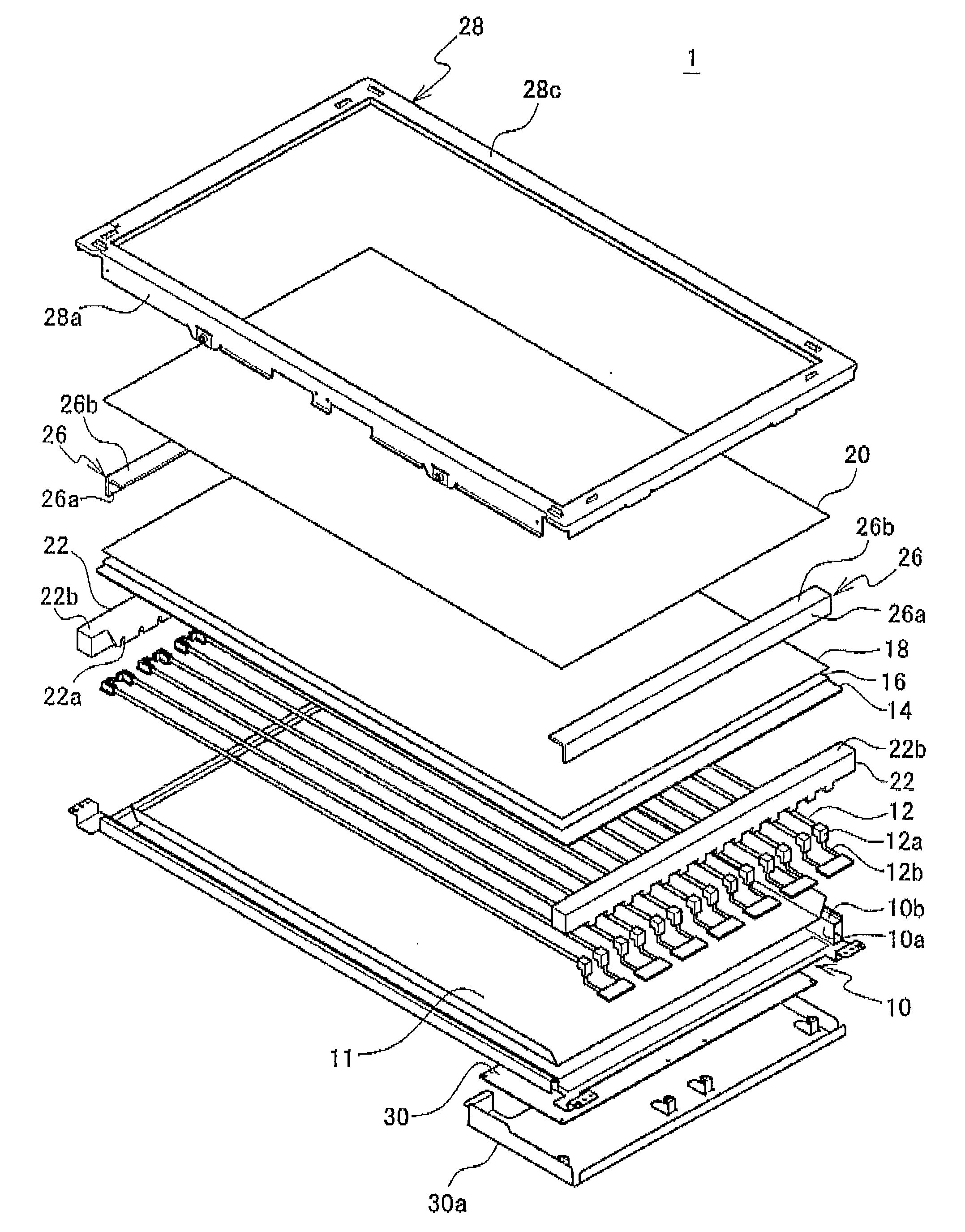
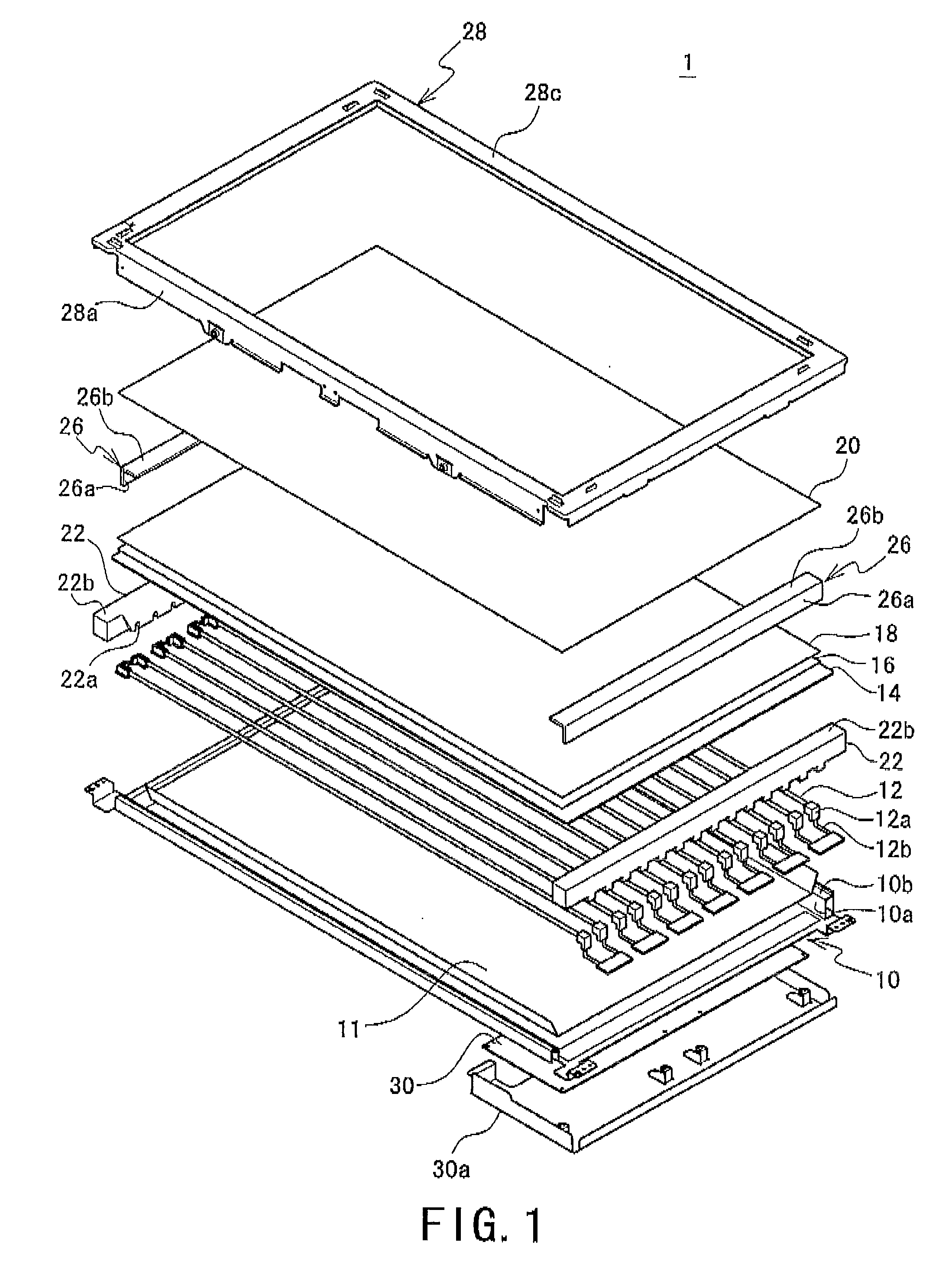
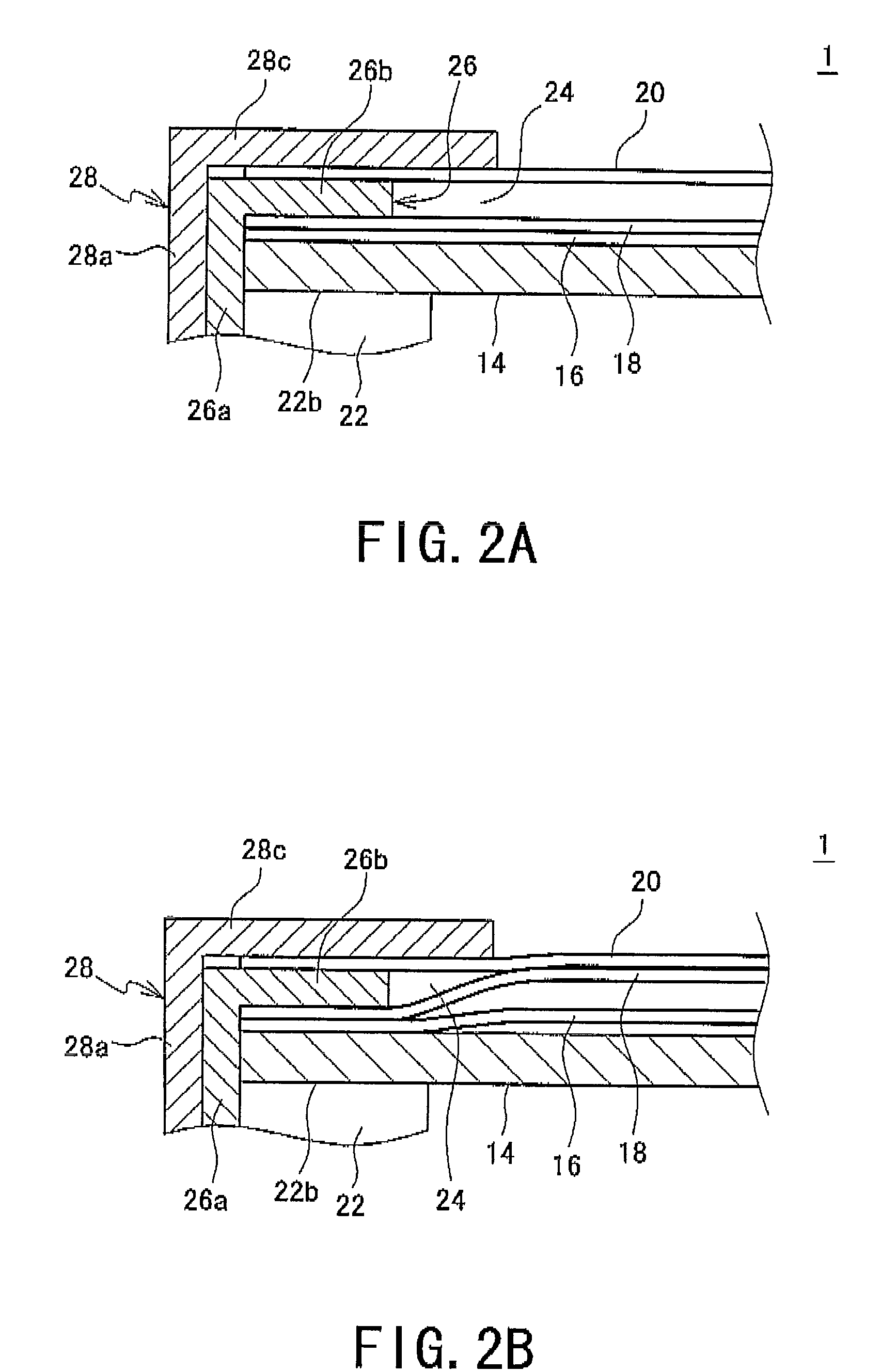
[0019]In the present invention, because the optical sheets are provided with the space for expansion which is arranged to accommodate a bend of the optical sheets which is caused by expansion of the optical sheets due to heat from the light source, the optical sheets tend to bend only toward the side where the space for expansion is provided when the optical sheets expand due to heat from the light source or other members. By intentionally providing a direction toward which the optical sheets tend to bend as described above, it is possible to inhibit the optical sheets from undulating due to thermal expansion. Accordingly, any bend of the optical sheets can be prevented from resulting in luminance nonuniformity and / or shades which are easy to visually perceive on the screen of the display panel.

Problems solved by technology

In addition, difference between the coefficient of thermal expansion of optical sheets and that of a member supporting the optical sheets may also cause a bend and / or a wrinkle of the optical sheets.
In the case of a structure where the optical sheets are supported by the supporting member at the edge portion, when the optical sheets and the supporting member are expanded by heat, the vicinity of the region supported by the supporting member of the optical sheets is pulled due to the difference in the coefficients of thermal expansion, causing a bend and / or a wrinkle.
If a bend and / or a wrinkle occur in the optical sheets, the bend and / or the wrinkle may result in luminance nonuniformity and / or shades on the front side of the display panel.
In particular, if the optical sheets bend repeatedly and thus undulates, or if a bend occurs in an optical sheet having directional optical properties such as a lens sheet, the luminance nonuniformity and / or shades on the screen are easy to visually perceive, which may degrade the display quality of the display device.
However, even with a backlight device having such a support configuration, there are some cases where a bend or a wrinkle cannot be prevented perfectly, depending on the conditions of thermal expansion of the optical sheets.
For example, if the temperature of the edge portion of the optical sheets differs from that of the center portion, the amount of thermal expansion may be nonuniform in accordance with the temperature distribution, which may result in nonuniform bends and / or wrinkles.
If the bending states are different as described above between the edge portion and the center portion of the optical sheets, it is difficult to remove the bends and / or wrinkles even if the edge portion of the optical sheets can freely alter its shape.
Consequently, it is very difficult to entirely remove bends and wrinkles of the optical sheets.

Method used


Image

  • Backlight device, display device, and television receiver
  • Backlight device, display device, and television receiver
  • Backlight device, display device, and television receiver

Examples


first modified embodiment

[0059]FIGS. 4A and 4B are views showing the present invention. Constituents common to the backlight device according to the preferred embodiment of the present invention described above are assigned the same reference numerals and descriptions thereof are omitted, and different constituents only are described.

[0060]FIG. 4A is an enlarged sectional view showing the vicinity of edge of the optical sheets 14, 16, 18, 20 in a state where a backlight device 1′ is assembled. The first diffusion sheet 16, the lens sheet 18, and the second diffusion sheet 20 are placed over the diffusion plate 14 (on the front side of the diffusion plate 14) which is placed on the support surface 22b of the side holder 22, and the spacer 26 is placed between the first diffusion sheet 16 and the lens sheet 18. The space 24 for expansion is thus provided between the first diffusion sheet 16 and the lens sheet 18. Accordingly, the space 24 for expansion is placed on one surface (the lower surface) of the lens ...


PUM


Abstract

A backlight device capable of preventing or reducing, even when an optical sheet bends, occurrence of luminance nonuniformity and / or shades due to the bend. The backlight device 1 controls the properties of light emitted by a light source 12 using two upper and lower diffusion sheets 16, 20 and a lens sheet 18 placed between the diffusion sheets and illuminates the back side of a display panel with the light, in which a space 24 for expansion is provided between the lens sheet 18 and the upper diffusion sheet 20, the space for expansion accommodating a bend of the lens sheet 18 which is caused by expansion due to heat from the light source 12.

Description

BACKGROUND OF THE INVENTION[0001]1. Field of the Invention[0002]The present invention relates to a backlight device and a display device and, more particularly, to a backlight device suitably used for a display device having a translucent display panel, and a display device having the backlight device.[0003]2. Description of the Related Art[0004]Some display devices including a non-self-emissive display panel such as a translucent liquid crystal display panel have a backlight device on the back side of the display panel. This backlight device includes a light source such as a fluorescent tube and predetermined kinds of optical sheets which control the properties of light emitted by the light source, and is arranged to illuminate the back side of the display panel with the light whose properties are controlled. The light illuminating the back side of the display panel passes through the display panel, making images displayed visible on the front side of the display panel, i.e., on th...

Claims


Application Information

Patent Timeline
IPC IPC(8): G02F1/1335G02F1/13357
CPCG02F2201/54G02F1/133606
Inventor TERAGAWA, DAISUKE
Owner SHARP KK
Learn More