
Projection display apparatus for suppressing speckle noise

Inactive Publication Date: 2010-01-21
SAMSUNG ELECTRO MECHANICS CO LTD
View PDF4 Cites 13 Cited by
  • Summary
  • Abstract
  • Description
  • Claims
  • Application Information

AI Technical Summary

Benefits of technology

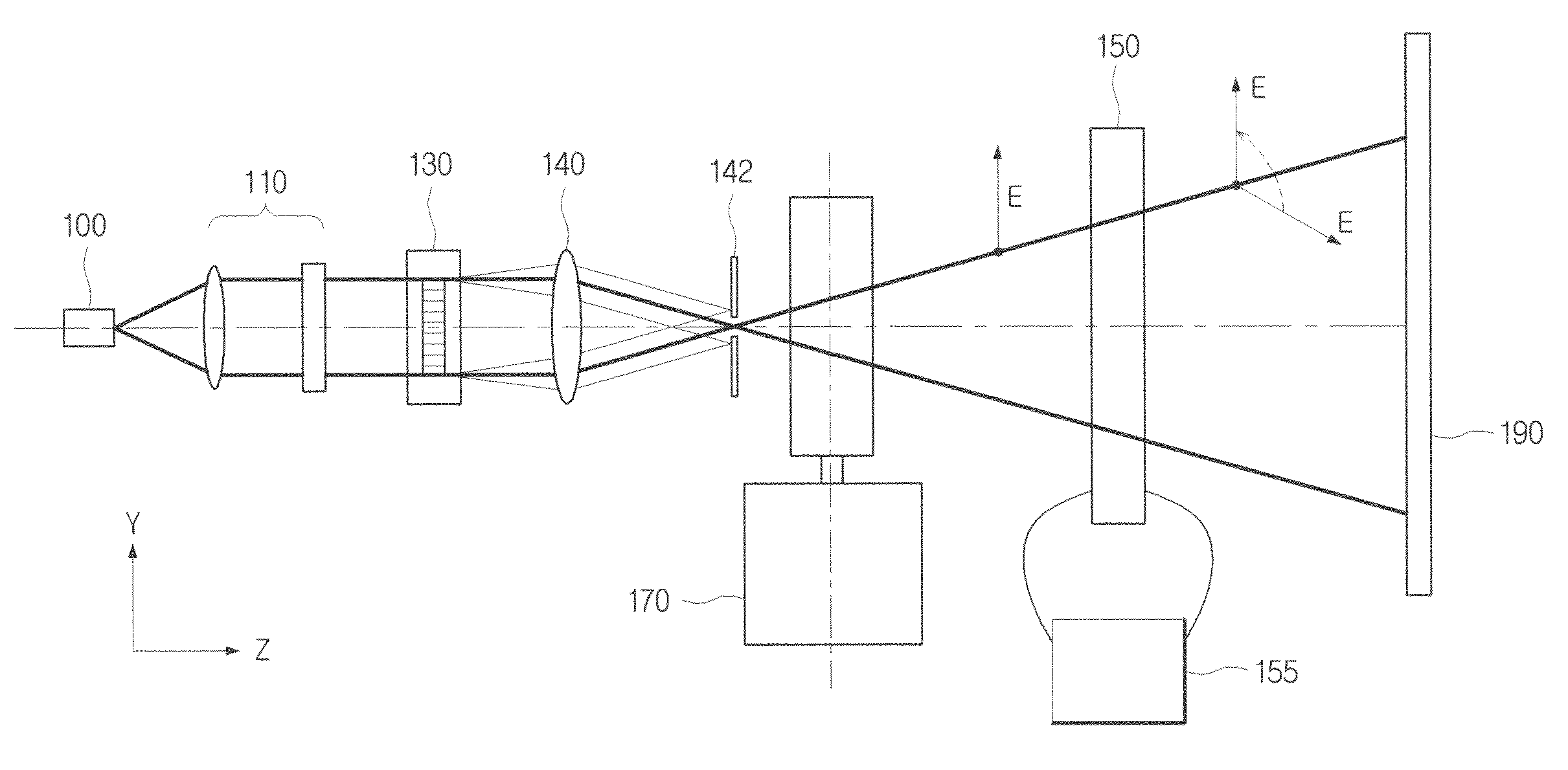
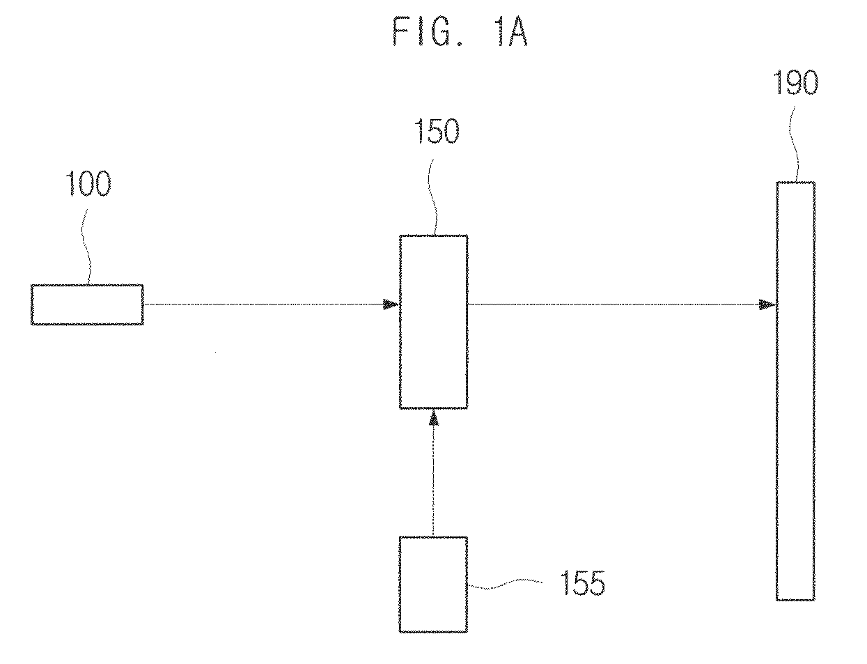
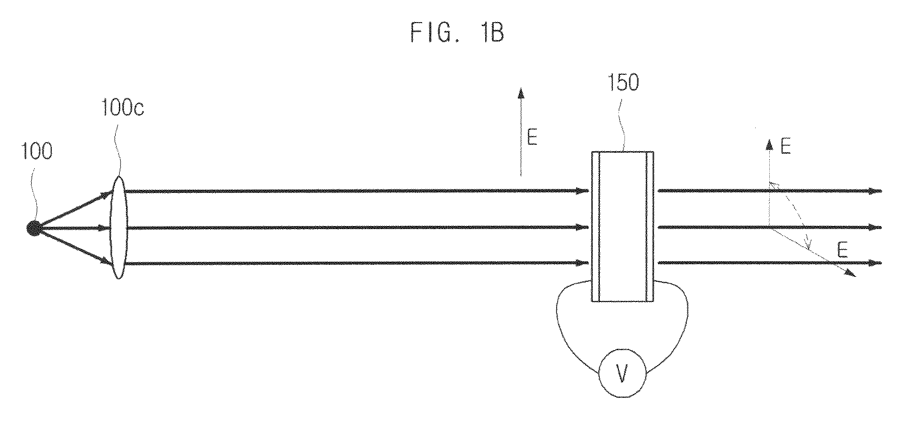
[0010]Accordingly, the present invention, which is contrived to solve the aforementioned problems, provides a projection display apparatus that can suppress speckle noises of a screen by time-dividedly rotating the direction of a polarized beam of light.

Problems solved by technology

It is very difficult that typical liquid crystal displays (LCD) or plasma display panels (PDP) realize the extra-large videos.
However, since such a projection display apparatus modulates a beam emitted from a laser light source per pixel and scans the beam to a screen in order to form a video, the formed video has a lower quality than those of other display apparatuses in which their screens directly emit rays of light.
One of the reasons that the formed video has the lower quality is resulted from a speckle noise or a speckle pattern generated on the video formed by a laser projection display apparatus.
The coherence of laser beams causes several interference patterns to be generated on a screen.
As a result, it is said that the quality of the video is significantly deteriorated.

Method used


Image

  • Projection display apparatus for suppressing speckle noise
  • Projection display apparatus for suppressing speckle noise
  • Projection display apparatus for suppressing speckle noise

Examples


Embodiment Construction

[0029]Since there can be a variety of permutations and embodiments of the present invention, certain embodiments will be illustrated and described with reference to the accompanying drawings. This, however, is by no means to restrict the present invention to certain embodiments, and shall be construed as including all permutations, equivalents and substitutes covered by the spirit and scope of the present invention.

[0030]Terms such as “first” and “second” can be used in describing various elements, but the above elements shall not be restricted to the above terms. The above terms are used only to distinguish one element from the other. For instance, the first element can be named the second element, and vice versa, without departing the scope of claims of the present invention. The term “and / or” shall include the combination of a plurality of listed items or any of the plurality of listed items.

[0031]When one element is described as being “connected” or “accessed” to another element...


PUM


Abstract

A projection display apparatus of the present invention can include a light source; an optical modulator, configured to repeatedly output a modulation beam N times in a predetermined time range, the modulation beam being generated by identically modulating a bema of light emitted from the light source and N being a nature number and equal to or greater than 2; a mirror, configured to reflect the modulation beam, which is repeatedly outputted N times, to scan the modulation beam to an identical point of a screen; and a polarization rotating unit, configured to rotate a polarization direction of the modulation beam for each time the modulation beam is scanned. With the present invention, the speckle noises on a video scanned to a screen can be suppressed.

Description

CROSS-REFERENCE TO RELATED APPLICATIONS[0001]This application claims the benefit of Korean Patent Application No. 10-2008-0070827 filed with the Korean Intellectual Property Office on Jul. 21, 2008, the disclosure of which is incorporated herein by reference in its entirety.BACKGROUND[0002]1. Technical Field[0003]The present invention relates to a projection display apparatus, more specifically to a projection display apparatus that can suppress speckle noises.[0004]2. Description of the Related Art[0005]Projection display apparatuses that employ a laser as their light sources are popular. The projection display apparatus can realize not only extra-large videos but also extra-small videos. It is very difficult that typical liquid crystal displays (LCD) or plasma display panels (PDP) realize the extra-large videos.[0006]However, since such a projection display apparatus modulates a beam emitted from a laser light source per pixel and scans the beam to a screen in order to form a vide...

Claims


Application Information

Patent Timeline
IPC IPC(8): G02B27/48G03B21/28
CPCG02B27/48H04N9/3167H04N9/3132G03B21/28H04N5/74
Inventor LAPCHUK, ANATOLIYYANG, HAENG-SEOKYURLOV, VICTOR
Owner SAMSUNG ELECTRO MECHANICS CO LTD
Learn More