

Power switchgear
a power switch and switchgear technology, applied in the direction of contact mechanisms, non-enclosed substations, substations, etc., can solve the problems of delay in mechanical movement, undesirable rotational angle, adversely affecting the mechanical properties of the circuit breaker
- Summary
- Abstract
- Description
- Claims
- Application Information
AI Technical Summary
Problems solved by technology
Method used
Image

Examples
first embodiment
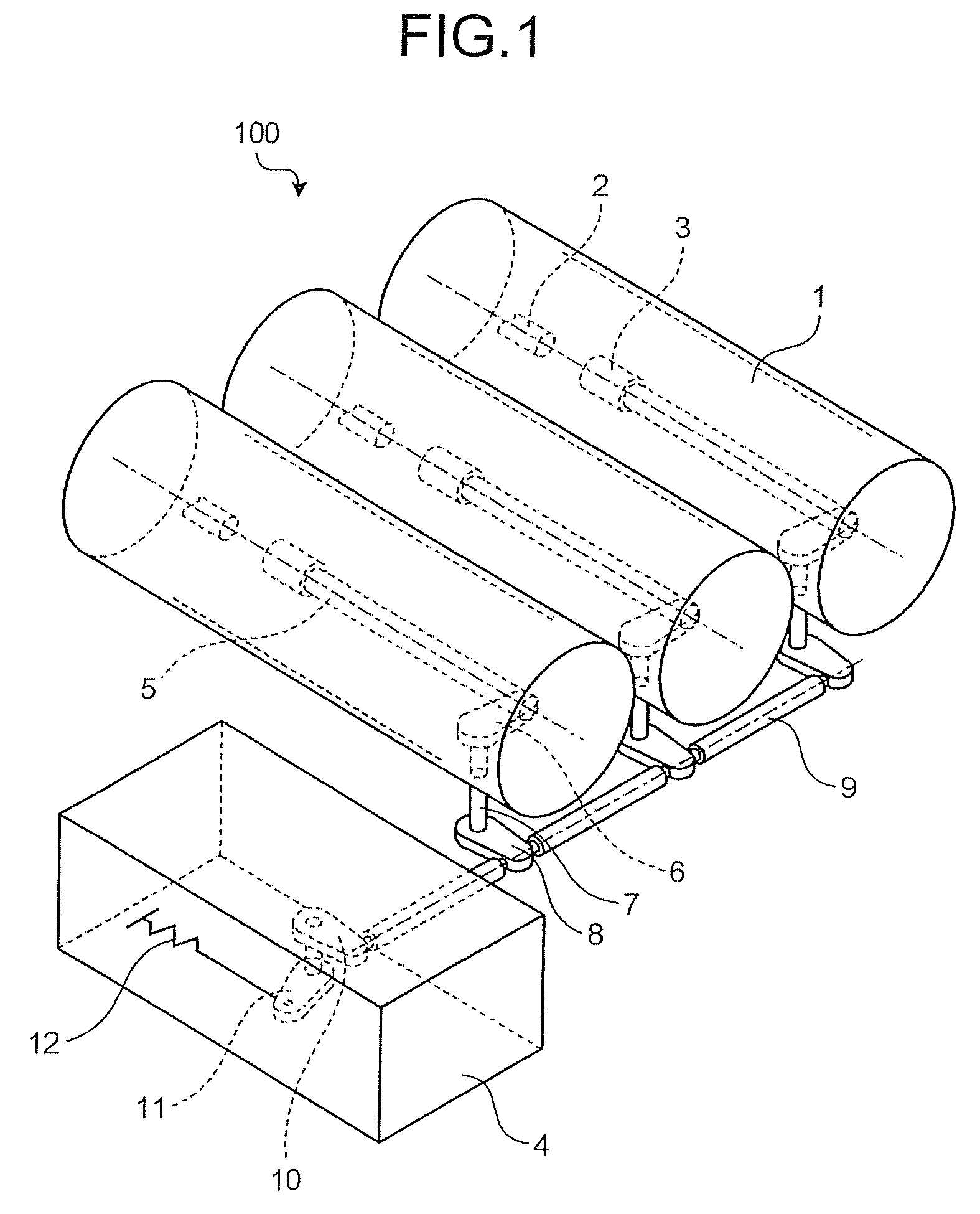
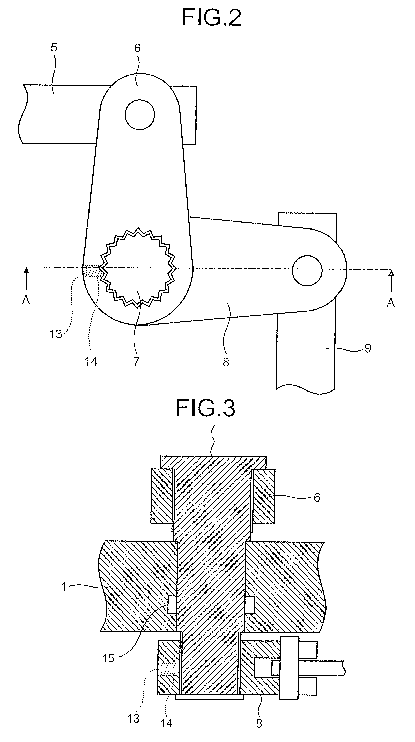
[0020]FIG. 1 is a perspective view of a switchgear 100 according to the present invention. The switchgear 100 includes grounding containers 1, an operation unit 4, stationary contacts 2, movable contacts 3, pressing elements 5, levers 6, rotary shafts 7, levers 8, linkage members 9, an output lever 10, a cutoff lever 11, and a spring 12.
[0021]The switchgear 100 is configured to open or close a circuit breaker per alternating current phase. For example, the switchgear 100 includes three grounding containers 1 and linkage units corresponding to the respective grounding containers 1 as shown in FIG. 1. The linkage units transmit a biasing force of the spring 12 to the movable contacts 3. Each of the linkage units includes, although not limited, the pressing element 5, the rotary shaft 7, the levers 6 and 8, and the linkage member 9. In addition, each of the linkage units includes a pressing member for pressing an outer periphery of the rotary shaft 7 against each mating inner periphery...
second embodiment
[0032]FIG. 4 is a plan view illustrating a state in which a rotary shaft 20 is engaged with the lever 6 (or the lever 8) according to the present invention. Other members associated with the rotary shaft. 20 and the levers 6 and 8 are as shown in FIG. 2.
[0033]The rotary shaft 20 is cylindrical and includes a number of axially segmented portions. An outer periphery of the rotary shaft 20 is gear shaped same as that of the rotary shaft 7 in the first embodiment. Moreover, an inner periphery of each of engaging holes in the levers 6 and 8 is gear shaped same as that of the rotary shaft 20, so that the outer periphery of the rotary shaft 20 is engaged with the inner periphery of the engaging hole in the lever 6 or 8.
[0034]FIG. 5 is a perspective view for explaining engagement of a columnar member 21 with an end portion of the rotary shaft 20. The columnar member 21 can be press-inserted into a hollow portion 22 (shown in FIG. 4) of the rotary shaft 20. When the columnar member 21 is pre...
third embodiment
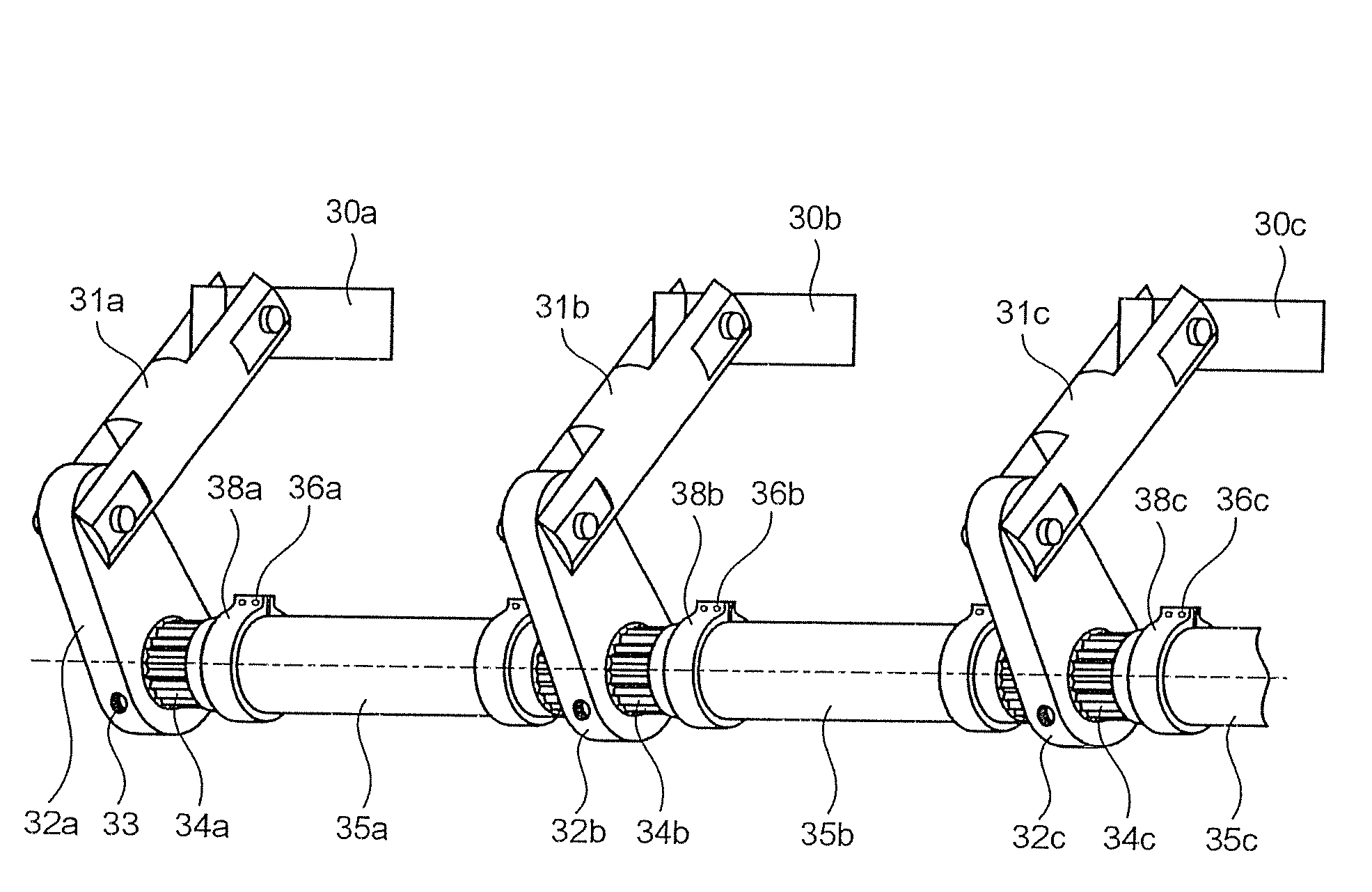
[0038]FIG. 7 is a perspective view of linkage units according to the present invention. Each of the linkage units corresponds to the pressing element 5, the lever 6, the rotary shaft 7, the lever 8, and the linkage member 9 shown in FIG. 1. In each of the linkage units shown in FIG. 7, either one of the lever 6 or 8, and the rotary shaft 7 are omitted. In place of the linkage members 9 shown in FIG. 1, rotary shafts 34a, 34b, and 34c, and coupling members 35a, 35b, and 35c are used for interconnecting phases.
[0039]The linkage unit that includes a pressing element 30a, a link 31a, and a lever 32a transmits a driving force to move the movable contact 3 of phase A shown in the left side in FIG. 1. The linkage unit for phase B (shown in the middle in FIG. 1) and the linkage unit for phase C (shown in the right side in FIG. 1) function in the same manner as the linkage unit for phase A.
[0040]The phases A and B are connected with a linkage rod unit including the rotary shaft 34a and the c...
PUM
 Abstract
Description
Claims
Application Information