Power supply equipment for fuel dispensing nozzle

a technology of power supply equipment and fuel dispensing nozzle, which is applied in the direction of flow control, instruments, packaging, etc., can solve the problems of affecting the operation of the fuel dispensing nozzle, the battery is small, the operation is also more critical, and the weight and bulk of the battery is larg

Inactive Publication Date: 2010-01-21
NOZZLE ENG
View PDF45 Cites 13 Cited by
  • Summary
  • Abstract
  • Description
  • Claims
  • Application Information

AI Technical Summary

Benefits of technology

[0019]Another object of the invention is to provide power supply equipment for a fuel dispensing nozzle which is reliable in operation for very long periods.
[0021]A further object of the invention is to provide power supply equipment for a fuel dispensing nozzle which is simple and economical to produce.
[0023]The invention makes it possible to supply power to a fuel dispensing nozzle in a safe and reliable way, without requiring expensive connecting wires to the electrical mains, and to achieve reliable operation which is practically unlimited in time.

Problems solved by technology

Nickel metal hydrate batteries are characterized by reasonable safety in operation and lower cost, but are relatively heavy and bulky; lithium ion batteries are smaller, lighter and more expensive, and their operation is also more critical.
Both types of battery have certain drawbacks in common, related mainly to the recharging circuit and shorter service life.
When rechargeable batteries are used in a fuel dispensing nozzle, there will be frequent recharges of a very partial nature, and therefore this application enables the number of recharges to be greatly increased, but it is difficult to achieve more than ten thousand recharges.
These factors have some particularly negative consequences for a nozzle for dispensing fuel, hazardous and / or highly flammable liquids or gas.
If a battery is overcharged, there may be releases of gas or, ultimately, even explosions.
Provision must also be made for replacing the battery, by forming a suitable hatch in the body of the nozzle; this not only increases the cost of the nozzle but also gives rise to problems relating to the requirements of robustness and sealing of equipment for dispensing fuel, hazardous and / or highly flammable liquids or gas.
The requirement for a store of replacement batteries is financially burdensome, especially as storage times for rechargeable batteries are limited and the batteries have a limited life.
However, this solution is difficult to implement, since it gives rise to considerable complications concerning installation.
For the purpose of explosion-proofing, the wired connection to the electrical mains must have special safety arrangements which make the wired connection very costly and impractical to produce.
The electrical connections along the fuel hose could also be subject to faults, bad contacts, interruptions, etc.

Method used


Image

  • Power supply equipment for fuel dispensing nozzle
  • Power supply equipment for fuel dispensing nozzle
  • Power supply equipment for fuel dispensing nozzle

Examples


Embodiment Construction

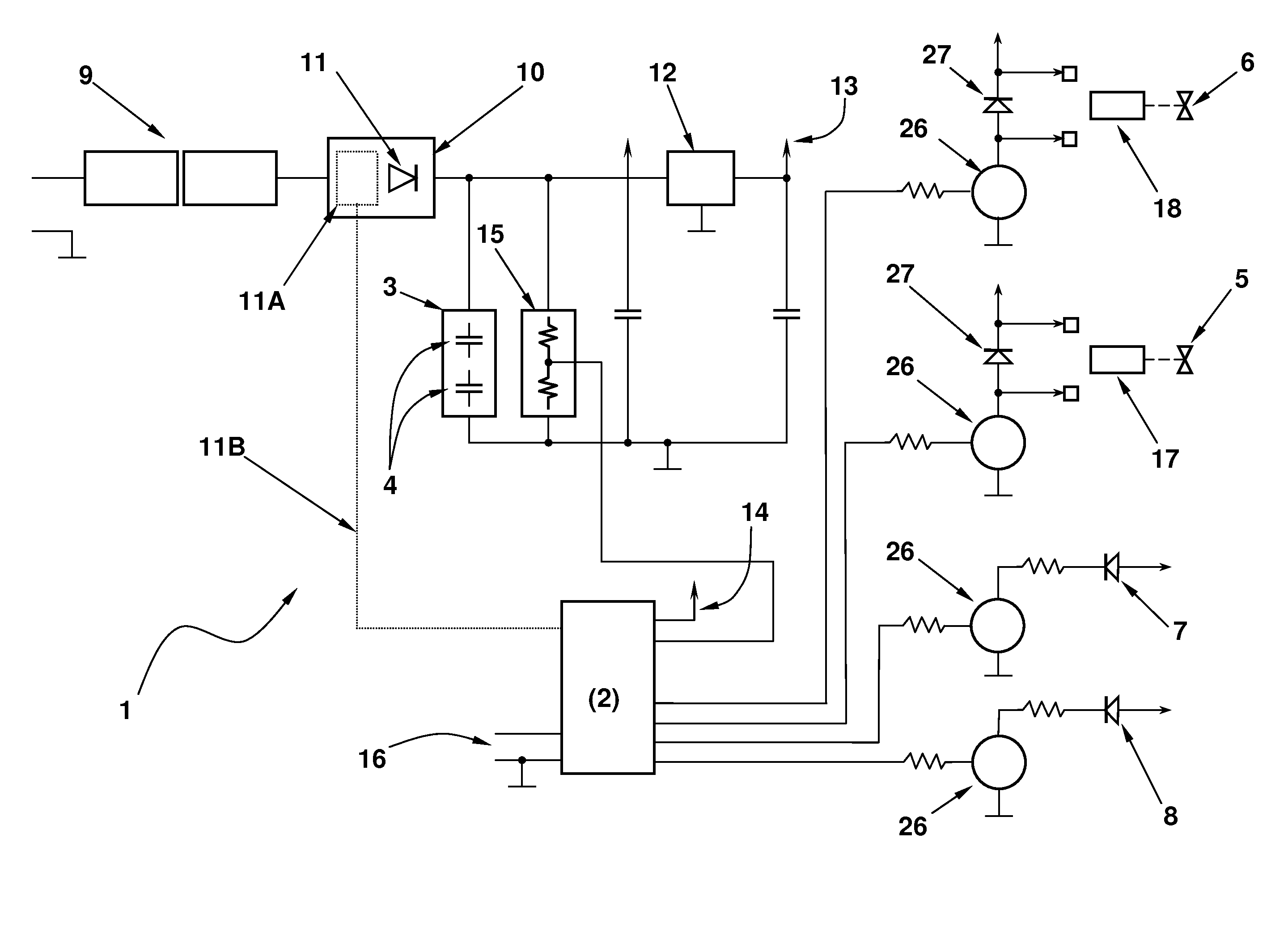
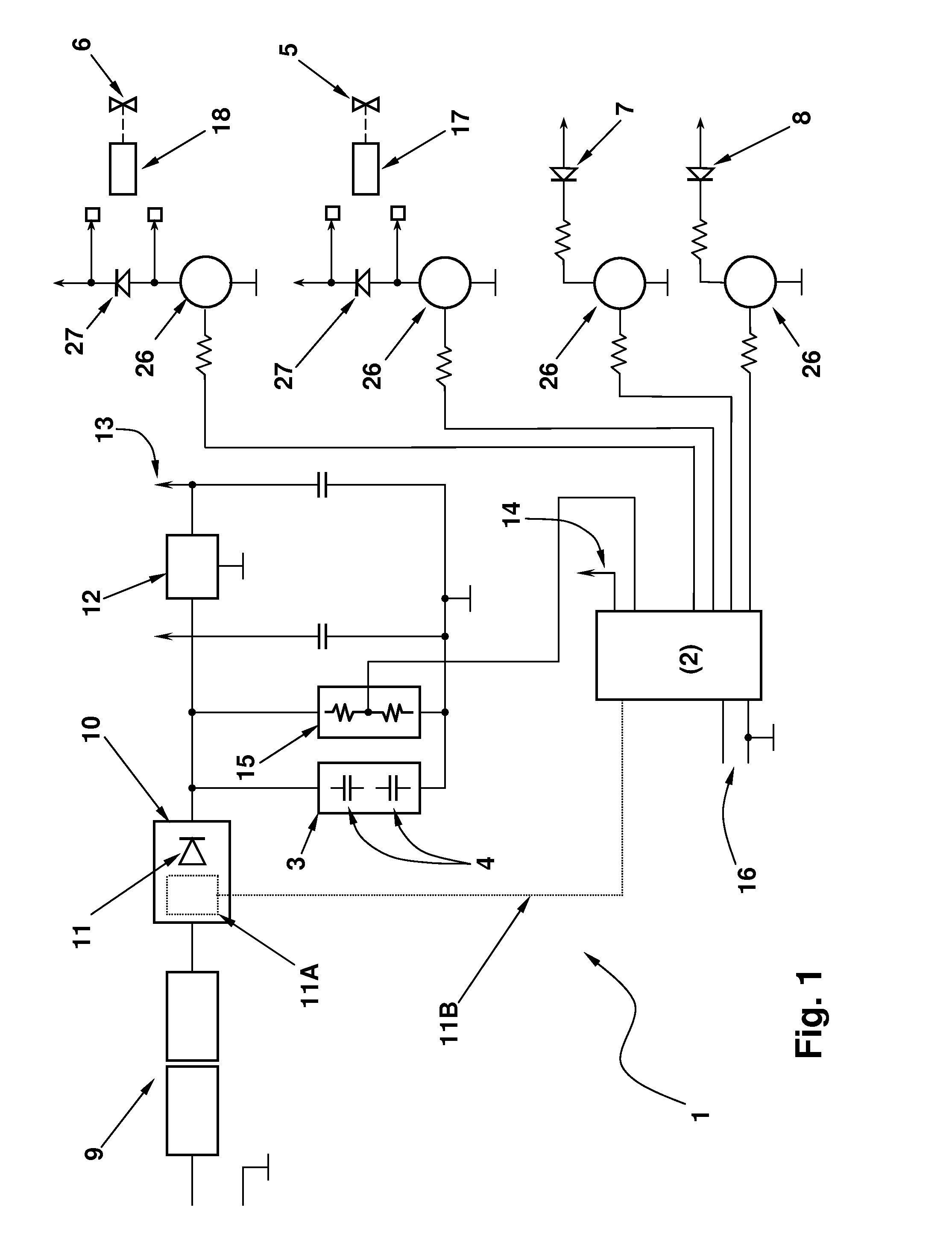
[0029]With reference to the drawings, the number 1 indicates the whole of the electrical equipment for a fuel dispensing nozzle (which is not shown).

[0030]The nozzle comprises a main solenoid-operated cut-off valve 5 which can open and close a pipe (not shown) for dispensing liquid or gaseous fuel, such as petrol, gas oil, kerosene, liquefied petroleum gas (LPG), methane, natural gas, hydrogen, etc., and a secondary solenoid valve 6 for dispensing a small flow of fluid, this secondary solenoid valve 6 being usable for topping up the fuel or in case of failure of the main solenoid valve.

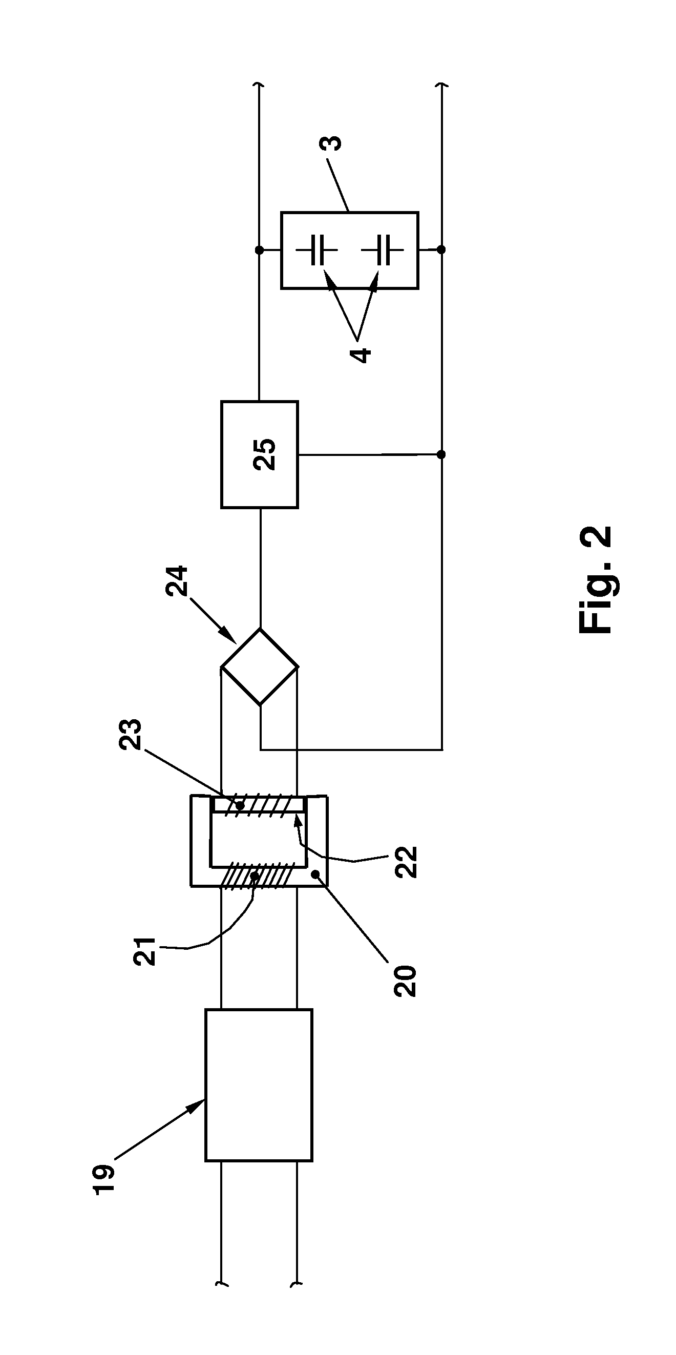
[0031]The electrical equipment 1 essentially comprises a microprocessor 2 and capacitor means 3.

[0032]The capacitor means 3 can comprise one or more supercapacitors 4. As is known, so-called supercapacitors, also called ultracapacitors, are capacitors with a very high electrical capacitance, generally above 0.1 farad, and small dimensions.

[0033]The capacitor means 3 supply power to the electrical comp...


PUM


Abstract

Power supply equipment for a fuels dispensing nozzle includes solenoid valves for dispensing fuel, a microprocessor for operating the solenoid valves and at least one supercapacitor or ultracapacitor for supplying power to the solenoid valves.

Description

TECHNICAL FIELD[0001]The present invention relates to power supply equipment for a fuel dispensing nozzle, particularly for a nozzle for dispensing liquid or gaseous fuel such as petrol, gas oil, kerosene, liquefied petroleum gas (LPG), methane, natural gas, hydrogen, etc.[0002]The power supply equipment according to the present invention is designed to provide a power supply for a fuel dispensing nozzle provided, for example, with a solenoid valve for dispensing fuel, or provided with other equivalent electrical means, such as electric motors, for dispensing fuel. More generally, the power supply equipment according to the present invention can be applied to an electrically operated device for dispensing hazardous and / or highly flammable liquids or gas.PRIOR ART[0003]Known fuel dispensing nozzles generally have mechanically and manually operated dispensing valves, and therefore require no power supply.[0004]U.S. Pat. No. 5,184,309 discloses an electrically operated fuel dispensing ...

Claims


Application Information

Patent Timeline
Patent Type & Authority Applications(United States)
IPC IPC(8): G05D11/00B67D7/32B67D7/28B67D7/42B67D7/46
CPCB67D7/425B67D7/32
Inventor BENTIVOGLIO, GALLIANO
Owner NOZZLE ENG
Why Eureka
Try Eureka