
Method for controlling intake of air-conditioner of vehicle

a technology for air conditioners and vehicles, applied in the direction of domestic cooling devices, lighting and heating devices, cooling fluid circulation, etc., can solve the problems of deteriorating air-conditioner performance, harming the health of passengers, interior of vehicles, etc., to improve heating efficiency and keep the indoor temperature of vehicles pleasant

Active Publication Date: 2010-01-28
HYUNDAI MOTOR CO LTD +1
View PDF1 Cites 8 Cited by
  • Summary
  • Abstract
  • Description
  • Claims
  • Application Information

AI Technical Summary

Benefits of technology

The present invention relates to a method for controlling an air-conditioner of a vehicle by allowing some indoor air to be introduced into the intake of the air-conditioner during the inflow of outdoor air, thus enhancing temperature control efficiency. This is achieved by manipulating a main door and a subsidiary indoor-air inlet port, which are opened or closed based on the driver's selection of an outdoor-air or indoor-air mode. The technical effect of this invention is to improve the performance of the air-conditioner in winter and to promote passenger health by circulating indoor air in the vehicle.

Problems solved by technology

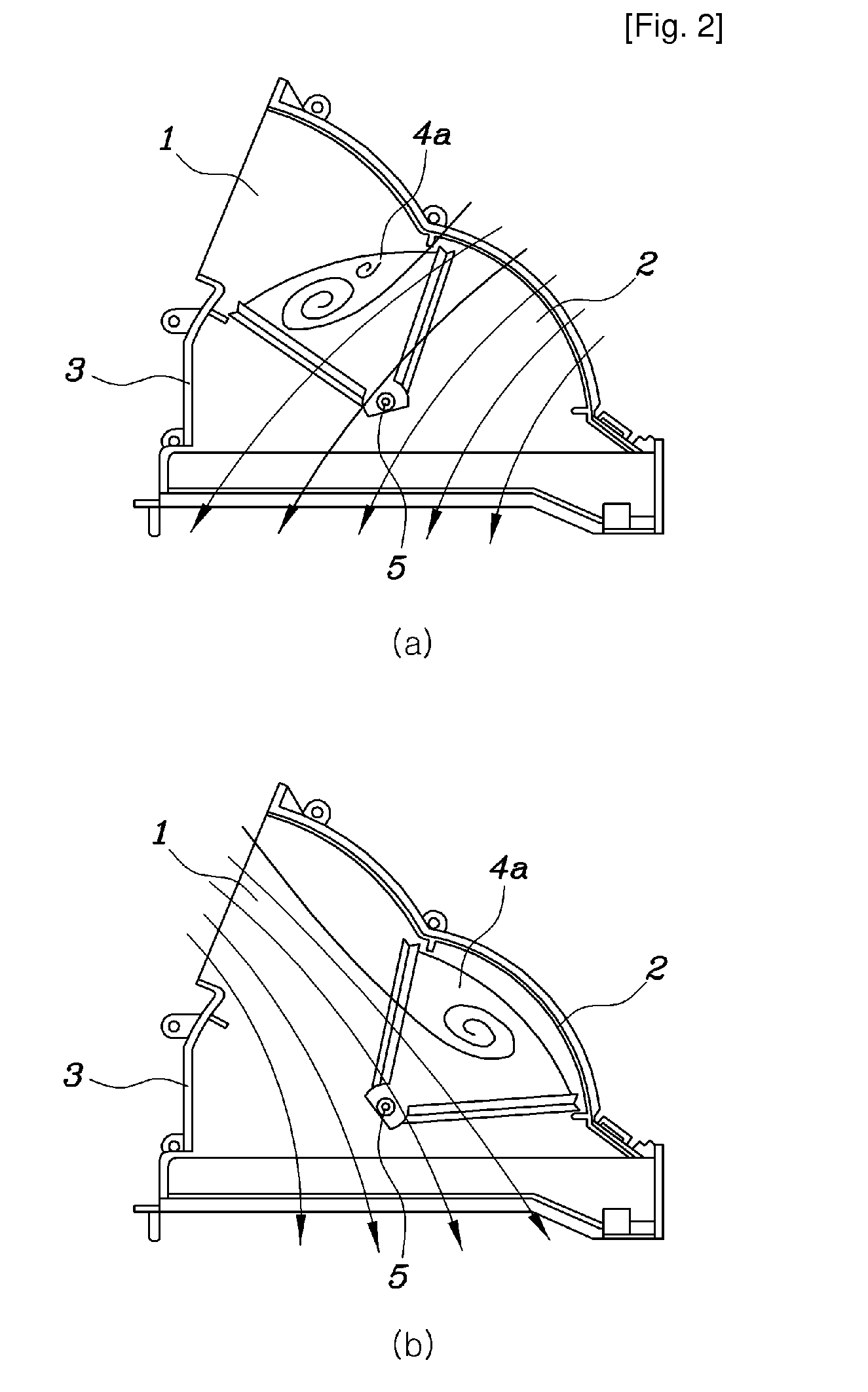
However, such an air-conditioner is problematic in that, if the outdoor-air mode is selected in winter, only outdoor air is fed into a vehicle through the outdoor-air inlet port 1 during the operation of the air-conditioner, so that the performance of the air-conditioner is deteriorated.
Further, when only indoor air circulates through the indoor-air inlet port, the interior of the vehicle becomes foul, thus harming a passenger's health.
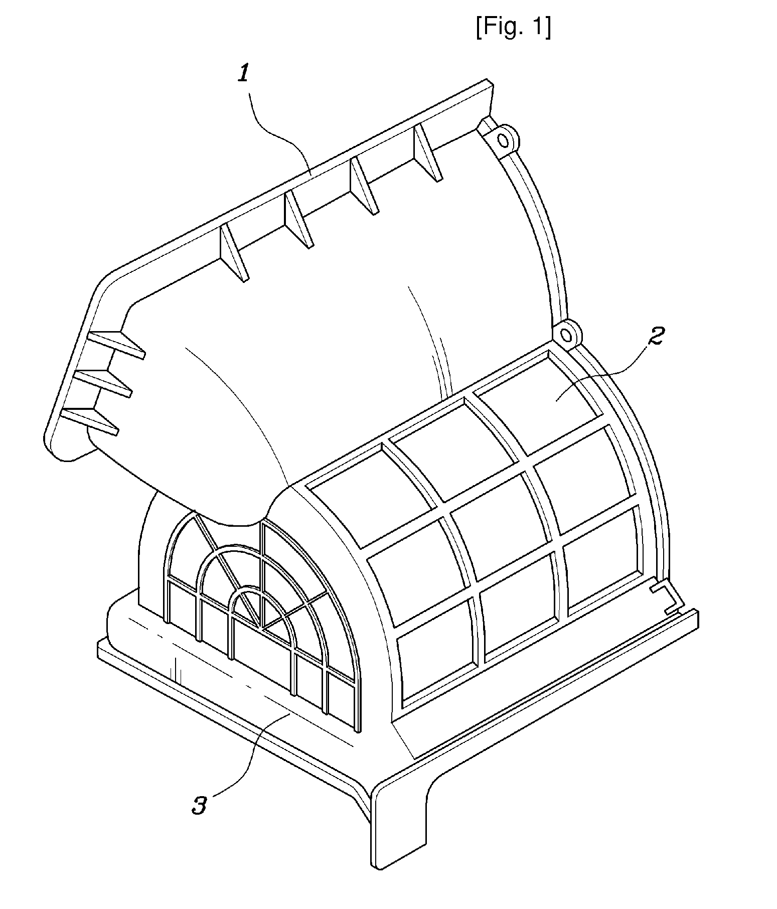
However, such an intake is problematic in that the main door 4b has the shape of a flat plate, so that it cannot be applied to the intake shown in FIGS. 1 and 2.
Thus, it is impossible to precisely control the quantity of indoor air that is drawn into the intake.

Method used


Image

  • Method for controlling intake of air-conditioner of vehicle
  • Method for controlling intake of air-conditioner of vehicle
  • Method for controlling intake of air-conditioner of vehicle

Examples


Embodiment Construction

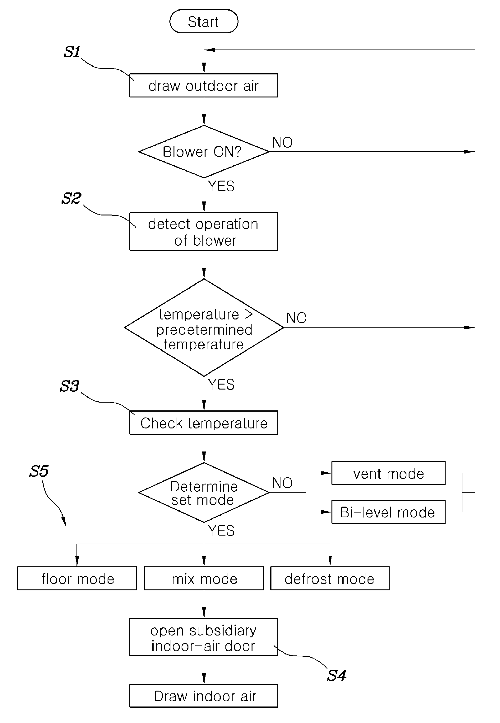
[0068]FIGS. 4 to 6 are flowcharts illustrating methods for controlling an intake of an air-conditioner of a vehicle, according to the present invention, FIG. 7 is a view showing an automatic-type control unit, and FIG. 8 is a view showing a manual-type control unit.

[0069]A method for controlling an intake of an air-conditioner of a vehicle according to the present invention controls an intake 200 of the air-conditioner, including an air-conditioner casing 100, a blower 130, and the intake 200, through steps that will be described below. The air-conditioner casing 100 has an evaporator 110 and a heater core 120 therein. A defrost vent 101, a face vent 102, and a floor vent 103 are formed in the outlet side of the air-conditioner casing 100. The blower 130 is provided on the inlet side of the air-conditioner casing 100. The intake 200 includes a housing 210, a main door 220, a subsidiary door 230, and a drive means. The housing 210 is installed to cover the blower 130. An outdoor-air ...


PUM


Abstract

A method for controlling an intake of an air-conditioner of a vehicle is disclosed. The method includes the a-1) step (S1) at which the main door (220) of the intake (200) opens the outdoor-air inlet port (211) and closes the indoor-air inlet port (212), so that only outdoor air flows into the intake, the b-1) step (S2) of detecting operation of the blower (130), the c-1) step (S3) of determining whether set indoor temperature of the vehicle is predetermined temperature or higher, and the d-1) step (S4) at which the subsidiary door (230) opens the subsidiary indoor-air inlet port (213) so that some indoor air flows into the intake. The method automatically controls the intake of the air-conditioner, thus allowing some indoor air to flow into the intake while outdoor air is flowing into the intake, therefore keeping the indoor temperature of the vehicle pleasant, and enhancing heating efficiency.

Description

TECHNICAL FIELD[0001]The present invention relates, in general, to a method for controlling an intake of an air-conditioner of a vehicle and, more particularly, to a method for controlling an intake of an air-conditioner of a vehicle, which allows some indoor air to be introduced into the intake together with outdoor air when a specific condition is satisfied during the inflow of the outdoor air, thus enhancing temperature control efficiency.BACKGROUND ART[0002]Generally, an air-conditioner for vehicles is an apparatus that draws air from inside and outside a vehicle, cools or heats the drawn air using a heat exchanger, and blows the air, which has undergone the heat exchange process, into the vehicle.[0003]Such an air-conditioner includes an air-conditioner casing, a blower, and an intake. An evaporator and a heater core are provided in the air-conditioner casing, and vents are provided on the outlet side of the air-conditioner casing. The opening ratio of each vent is controlled b...

Claims


Application Information

Patent Timeline
Patent Type & Authority Applications(United States)
IPC IPC(8): F25D17/04B60H1/00
CPCB60H1/00849B60H1/00807B60H1/00828
Inventor CHOI, JAE SIKKIM, HAK KYULEE, DONG WON
Owner HYUNDAI MOTOR CO LTD
Learn More