Fusible link unit

a technology of fusible link unit and bus bar, which is applied in the direction of basic electric elements, emergency protective devices, emergency protective circuit arrangements, etc., can solve the problems of complex stock management of the plurality of kinds of fusible link units b>110/b>, high cost of each bus bar, etc., and achieve the effect of low cos

Active Publication Date: 2010-01-28
YAZAKI CORP
View PDF13 Cites 26 Cited by
  • Summary
  • Abstract
  • Description
  • Claims
  • Application Information

AI Technical Summary

Benefits of technology

[0032]In the fusible link unit of the first to fifth aspects of the invention, the bus bar made of the electrically-conductive metal sheet has the battery terminal formed at the one end portion thereof and adapted to be fastened to the battery post-clamping terminal member clamped to the battery post of the on-vehicle battery, and also has at least one fusible portion connected to the other end portion of the bus bar disposed rearwardly of the battery terminal, and the fusible portion can melt when an over-current flows therethrough. Particularly, at least two mounting edges are formed at the outer periphery of the battery terminal so that the battery post-clamping terminal member can be fastened to the battery terminal from a selected one of the different directions, and the fastening hole for the passage of the fastening member therethrough so as to fasten the battery post-clamping terminal member to the battery terminal is formed through the battery terminal. Therefore, the bus bar can be suitably used in any of a plurality of kinds of vehicles, and the fusible link unit of the invention can be provided at a low cost. The fastening hole formed through the terminal battery can have any of the twofold leaf-shape, the trefoil shape and the rectangular shape (each having the fastening member-receiving portions (hole portions) opposed respectively to the mounting edges) or the round shape such that the position of the fastening hole relative to the mounting edges can be varied.
[0033]In the fusible link unit of the sixth aspect of the invention, the bus bar made of the electrically-conductive metal sheet has the battery terminal formed at the one end portion thereof and adapted to be fastened to the battery post-clamping terminal member clamped to the battery post of the on-vehicle battery, and also has at least one fusible portion connected to the other end portion of the bus bar disposed rearwardly of the battery terminal, and the fusible portion can melt when an over-current flows therethrough. Particularly, the battery terminal includes the inclined mounting edge extending from the end of the distal end edge thereof (so disposed as to be generally parallel to the one side surface of the on-vehicle battery) toward the one side surface of the on-vehicle battery and inclined at the predetermined angle relative to the distal end edge, and the battery post-clamping terminal member is fastened to the battery terminal in opposed relation to the inclined mounting edge. Therefore, when the batter post-clamping terminal member is to be clamped to the battery post of the on-vehicle battery mounted, for example, within a trunk room of the vehicle, the operation side in the clamping operation can be directed toward the operator, and therefore the battery post-clamping terminal member can be efficiently and positively clamped to the battery post of the on-vehicle battery, and also the area of installation of the fusible link unit on the on-vehicle battery can be reduced.

Problems solved by technology

As a result, the cost of each bus bar 111 is high, and besides a stock management of the plurality of kinds of fusible link units 110 is complicated.

Method used


Image

  • Fusible link unit
  • Fusible link unit
  • Fusible link unit

Examples


first exemplary embodiment

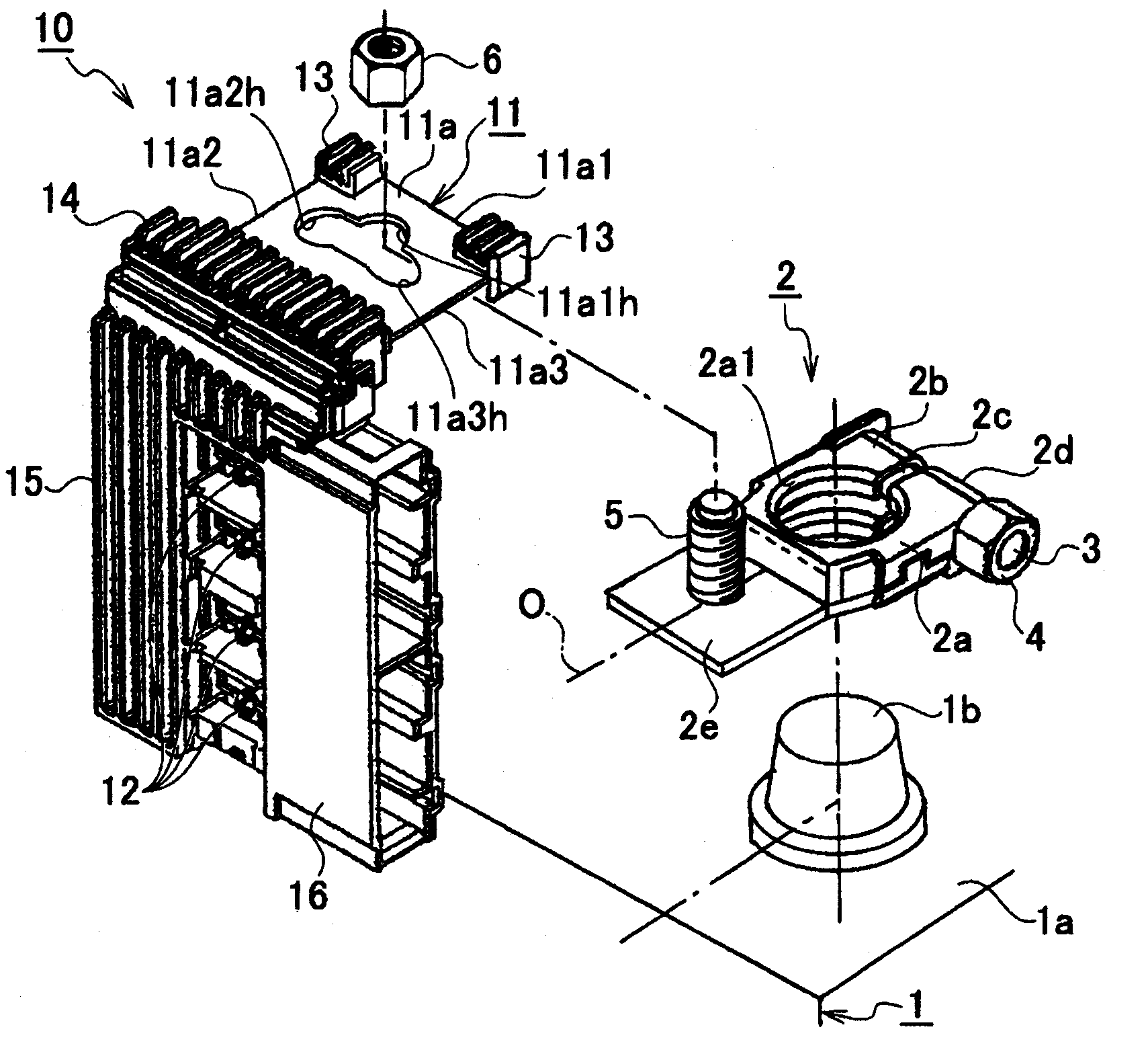
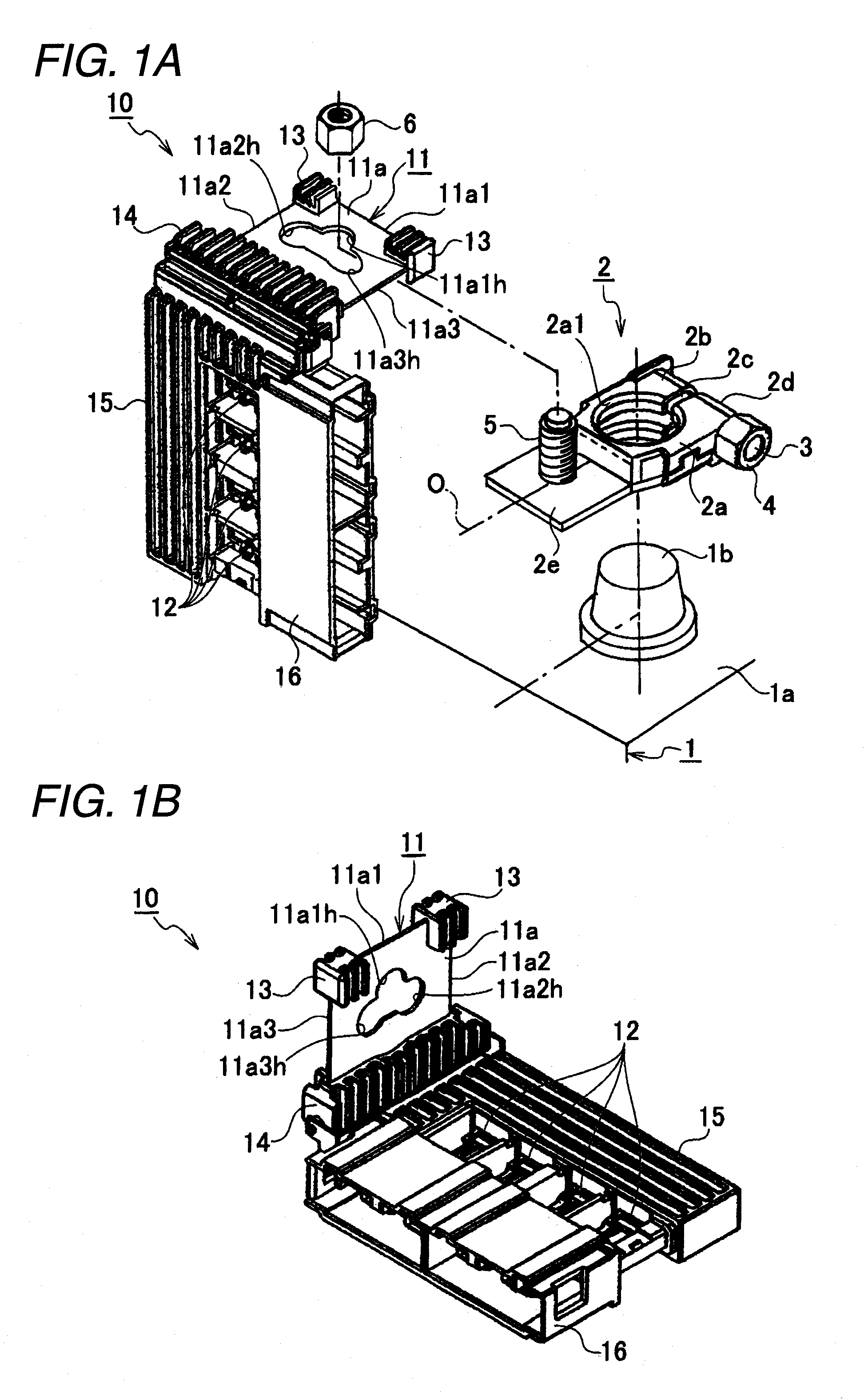
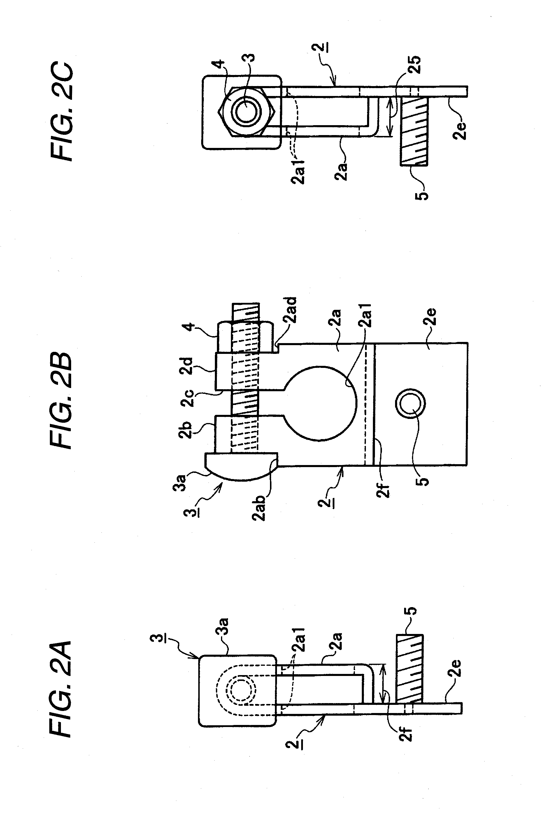
[0052]FIGS. 1A and 1B are explanatory views of the first embodiment of the fusible link unit of the invention. FIG. 1A is an exploded perspective view showing a condition in which the fusible link unit of the first embodiment is to be mounted on a battery post of an on-vehicle battery through a battery post-clamping terminal member. FIG. 1B is a perspective view of the fusible link unit of the first embodiment as seen from the reverse side thereof FIGS. 2A, 2B and 2C are a left side-elevational view, a top plan view and a right side-elevational view of the battery post-clamping terminal member of FIG. 1, respectively. FIG. 3 is a developed view of an electrically-conductive bus bar employed in the fusible link unit of the first embodiment. FIGS. 4A, 4B and 4C are explanatory views of a first form of use of the fusible link unit of the first embodiment. FIG. 4A is a plan view showing the first form of use of a battery terminal of the bus bar. FIG. 4B is a perspective view showing the...

second exemplary embodiment

[0093]FIG. 8 is a plan view showing a condition in which a second embodiment of a fusible link unit of the invention is mounted on a battery post of an on-vehicle battery through a battery post-clamping terminal member, and FIG. 9 is a plan view showing a condition in which the fusible link unit of the second embodiment is mounted on the battery post of the on-vehicle battery through the battery post-clamping terminal member when the on-vehicle battery is mounted within a trunk room of a vehicle.

[0094]As shown in FIG. 8, in the fusible link unit 20 of the second embodiment, a bus bar 21 including a battery terminal 21a and at least one fusible portion 22 so as to form a bus bar. The battery terminal 21a is fastened to a battery post-clump terminal member 2 which is clumped to a battery post 1b of a on-vehicle battery. The battery terminal 21a is formed at one end side of a conductive metal plate. The fusible portion 22 is fused when an over current flows on another end side which is...

third exemplary embodiment

[0105]FIG. 10 is an exploded perspective view showing a condition in which a third embodiment of a fusible link unit of the invention is to be mounted on a battery post of an on-vehicle battery through a battery post-clamping terminal member, and FIG. 11 is a plan view showing the fusible link unit of the third embodiment, and FIG. 12A is a view showing a first form of use, in which the fusible link unit of the third embodiment is mounted on the battery post of the on-vehicle battery through the battery post-clamping terminal member, and FIG. 12B is a view showing a second form of use, in which the fusible link unit of the third embodiment is mounted on the battery post of the on-vehicle battery through the battery post-clamping terminal member, and FIG. 13 is an enlarged plan view showing a battery terminal formed at one end portion of a bus bar employed in the fusible link unit of the third embodiment.

[0106]As shown in FIG. 10, in the fusible link unit 30 of the third embodiment, ...


PUM


Abstract

A fusible link unit which is fastened to a battery post clamp terminal clamped to an on-vehicle battery, includes: a bus bar made from a metal plate and including: a battery terminal including at least two mounting edges, and a plurality of fastening holes provided thereon and through which a fastening member of the battery post clamp terminal is inserted, each of the fastening holes corresponding to respective one of the mounting edges; and at least one fusible portion provided at an side of the bus bar opposite to the battery terminal; and a resin case covering the bus bar except for at least one of the fusible portion.

Description

CROSS-REFERENCE TO RELATED APPLICATIONS[0001]This application claims priority from Japanese patent application No. 2008-192643 filed on Jul. 25, 2008, the entire subject matter of which is incorporated herein by reference.TECHNICAL FIELD[0002]This invention relates to a fusible link unit including a battery terminal and at least one fusible portion so as to form a bus bar. The battery terminal is combined with a battery post-clump terminal member which is clumped to a battery post of a on-vehicle battery. The battery terminal is formed at one end side of a conductive metal plate. The fusible portion is fused when an over current flows on another end side which is rearward of the metal plate as compared to the battery terminal. The bas bar is able to be commonly used for a plurality kinds of vehicles.BRIEF DESCRIPTION OF THE RELATED ART[0003]Generally, an on-vehicle battery serving as a drive source for driving an electrical system is mounted within a bonnet or a trunk room of a vehi...

Claims


Application Information

Patent Timeline
Patent Type & Authority Applications(United States)
IPC IPC(8): H02H7/18
CPCH01H85/044H01H2085/0555H01H2085/025
Inventor KUDO, TOSHIHARUMATSUMURA, NORIOIWATA, MASASHIFUJII, DAIGORONOMURA, SYOUICHIAOKI, TATSUYA
Owner YAZAKI CORP
Why Eureka
Try Eureka