Scanning backlight for LCD

a backlight and scanning technology, applied in the field of methods and displays, can solve the problems of blurred image of objects on the retina of a viewer, motion blur in the lcd (liquid crystal display) panel, etc., and achieve the effect of improving the display

Inactive Publication Date: 2010-01-28
KONINKLIJKE PHILIPS ELECTRONICS NV
View PDF6 Cites 50 Cited by
  • Summary
  • Abstract
  • Description
  • Claims
  • Application Information

AI Technical Summary

Benefits of technology

[0003]It is therefore an object of the present invention to provide an improved method for displaying images on a display, and an improved display.

Problems solved by technology

LCD (Liquid Crystal Display) panels suffer from motion blur due to their sample-and-hold nature, i.e. the LC (Liquid Crystal) remains in the same state after addressing during a whole frame.
When displayed objects move, as is the case in e.g. TV images, this causes a blurred image of the objects on the retina of a viewer.

Method used


Image

  • Scanning backlight for LCD
  • Scanning backlight for LCD
  • Scanning backlight for LCD

Examples


Embodiment Construction

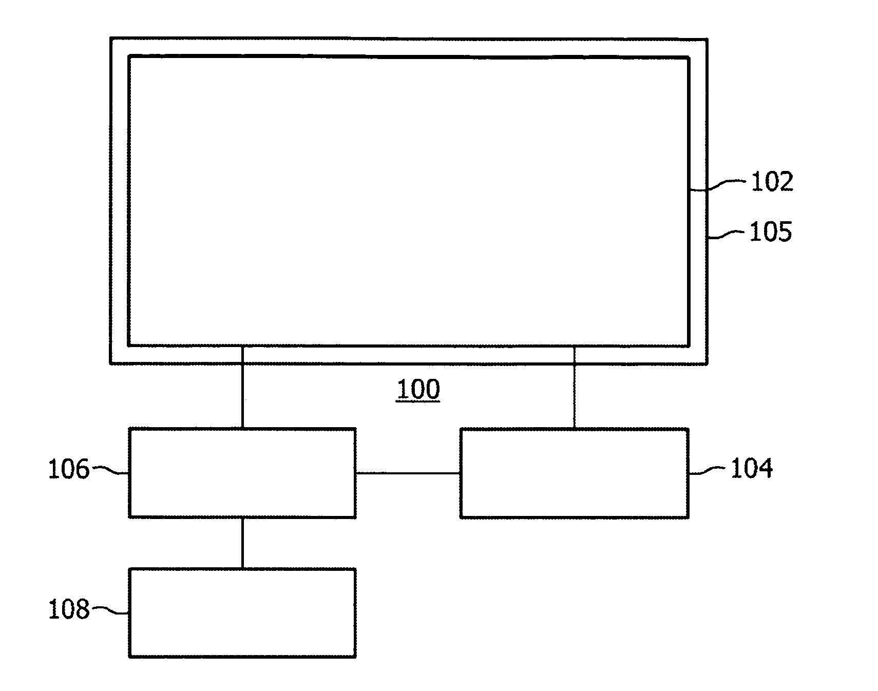
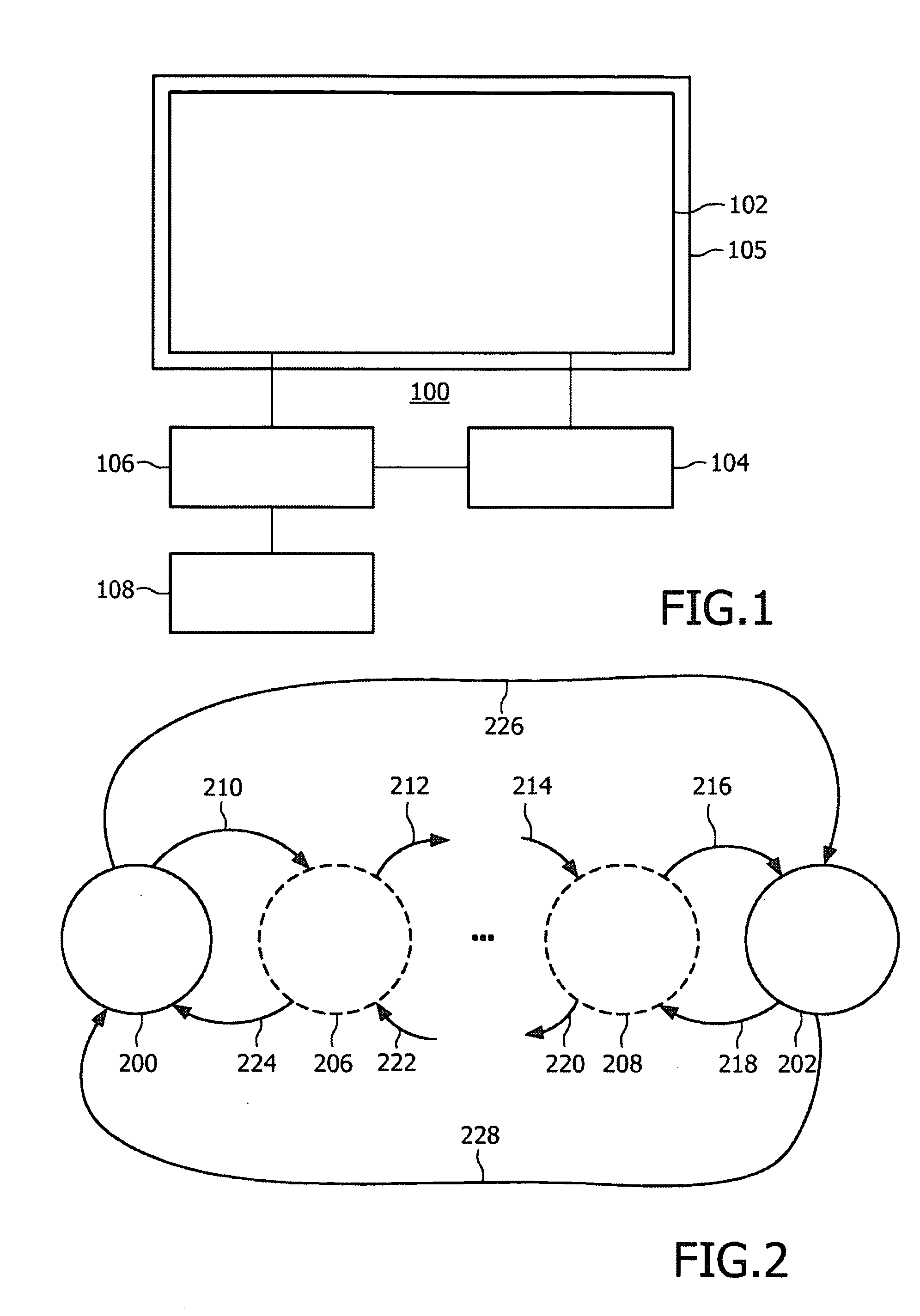
[0034]FIG. 1 illustrates a display 100 comprising a display panel 102. The display panel 102, which can be a LCD (Liquid Crystal Display) panel, is provided with backlighting 105. The backlighting 105 can for example comprise one or more light sources (not shown), such as light emitting diodes (LEDs) or gas discharge lamps. The backlight is flashed, either for the entire panel 102 or, preferably, by scanning backlight segments of the panel 102. Thus, an LC cell is illuminated only for a certain fraction of the frame time. A backlight controller 104, which is connected to the backlighting 105 of the panel 102, controls backlight flashing. To avoid large area flicker, the backlight controller 104 provides a backlight control signal which is dependent on an image displayed on the panel102. Therefore, the backlight controller 104 is connected to a display controller 106, which in turn receives image data from an image data source 108. It should be noted that this description is for illu...


PUM


Abstract

A method for displaying images on a display having backlight is disclosed, where the images is updated periodically with a period. The method comprises the steps of: generating a signal with a pulse pattern for each period depending on the contents of an image to be displayed in that period; and activating backlight in accordance with the signal. Further, a display (100) comprising a display panel (102) and a backlight unit, wherein the backlight unit comprises a controller (104) and a lighting device is disclosed. The controller (104) is arranged to generate a control signal, and the lighting device is arranged to provide backlight to the display panel (102) according to the control signal, wherein the control signal comprises a pulse pattern depending on contents of displayed images.

Description

TECHNICAL FIELD[0001]The present invention relates to a method and a display, wherein backlight is generated depending on contents of displayed images.BACKGROUND OF THE INVENTION[0002]LCD (Liquid Crystal Display) panels suffer from motion blur due to their sample-and-hold nature, i.e. the LC (Liquid Crystal) remains in the same state after addressing during a whole frame. When displayed objects move, as is the case in e.g. TV images, this causes a blurred image of the objects on the retina of a viewer. In US 2004 / 0012551 A, it is disclosed a means to drive the data for the value corresponding to a present frame display data. By comparing with previous frame of display data, the display data in the present frame that have changes are then over emphasized and written into the LCD driver with more than the amount of change to the picture element data. Further, a backlight control means to control the lighting delay time, the lighting time width, the lighting time interval and the numbe...

Claims


Application Information

Patent Timeline
Patent Type & Authority Applications(United States)
IPC IPC(8): G09G3/36
CPCG09G3/342G09G2310/024G09G2320/0247G09G2320/106G09G2320/062G09G2320/0633G09G2320/064G09G2320/0261G02F1/133G09G3/34
Inventor VAN WOUDENBERG, ROELGROOT HULZE, HENDRIKUS WILLEMSTESSEN, JEROEN HUBERT CHRISTOFFEL JACOBSEVO, ALEKSANDARHEKSTRA, GERBEN JOHANBLANKERS, HENDRIK JANKOVACEVIC, VEDRANDEN BREEJEN, JEROEN
Owner KONINKLIJKE PHILIPS ELECTRONICS NV
Why Eureka
Try Eureka