Vibrator with a variable moment using a phase shifter with reduced clearances

a technology of phase shifter and variable moment, which is applied in the direction of bulkheads/piles, construction, foundation engineering, etc., can solve the problems of immobilization of equipment, burdening the operating cost of parts replacement and maintenance, and the structure of the vibrator is not optimized in terms of maintenance, so as to relieve the phase shifter

Inactive Publication Date: 2010-02-04
PARAMETRIC TECH CORP
View PDF6 Cites 6 Cited by
  • Summary
  • Abstract
  • Description
  • Claims
  • Application Information

AI Technical Summary

Benefits of technology

[0036]With this assembly, it is possible to ensure transmission of the forces related to the operation of the vibrator between both sidewalls and the tubular transmission part, thereby relieving the phase shifter.

Problems solved by technology

Although this solution is satisfactory, it has a number of drawbacks.
Indeed, as the vibratory context is very demanding for mechanical parts, experience has shown that moving parts are subject to significant wear; the latter therefore have frequent maintenance and thus burden the operating costs in terms of replacement of parts and immobilization of the equipment.
The structure of the vibrator, as described earlier, is not optimized in terms of maintenance taking into account the reduced accessibility to the phase shifter and to the moving parts, the latter for the most part, being particularly bulky and heavy.
Moreover, it is found that the stresses exerted at the cogs for driving the shafts comprising eccentric flyweight trains, are for the most part transmitted to the phase shifter; which is structurally fragile taking into account the moving parts hydraulically sealed and therefore particularly toleranced.

Method used


Image

  • Vibrator with a variable moment using a phase shifter with reduced clearances
  • Vibrator with a variable moment using a phase shifter with reduced clearances
  • Vibrator with a variable moment using a phase shifter with reduced clearances

Examples


Embodiment Construction

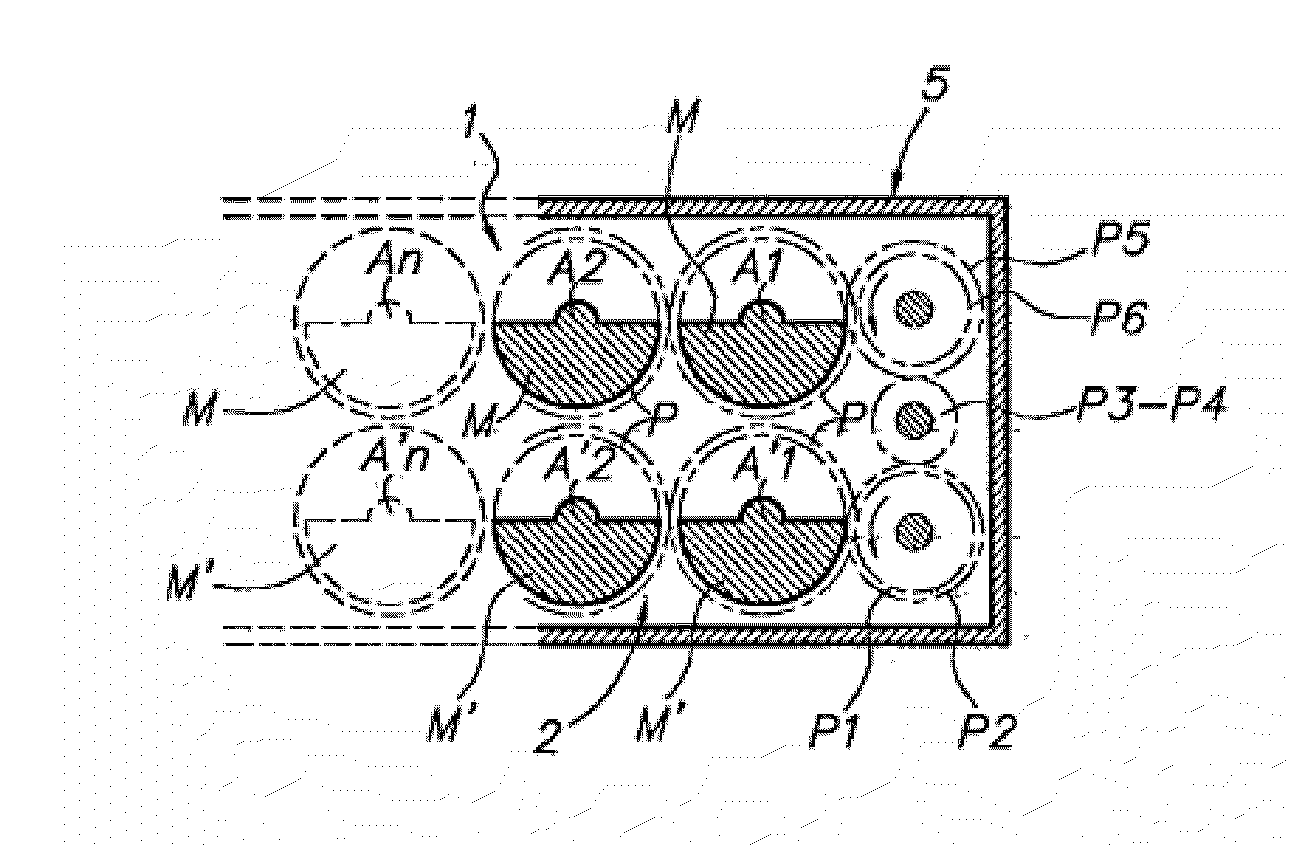
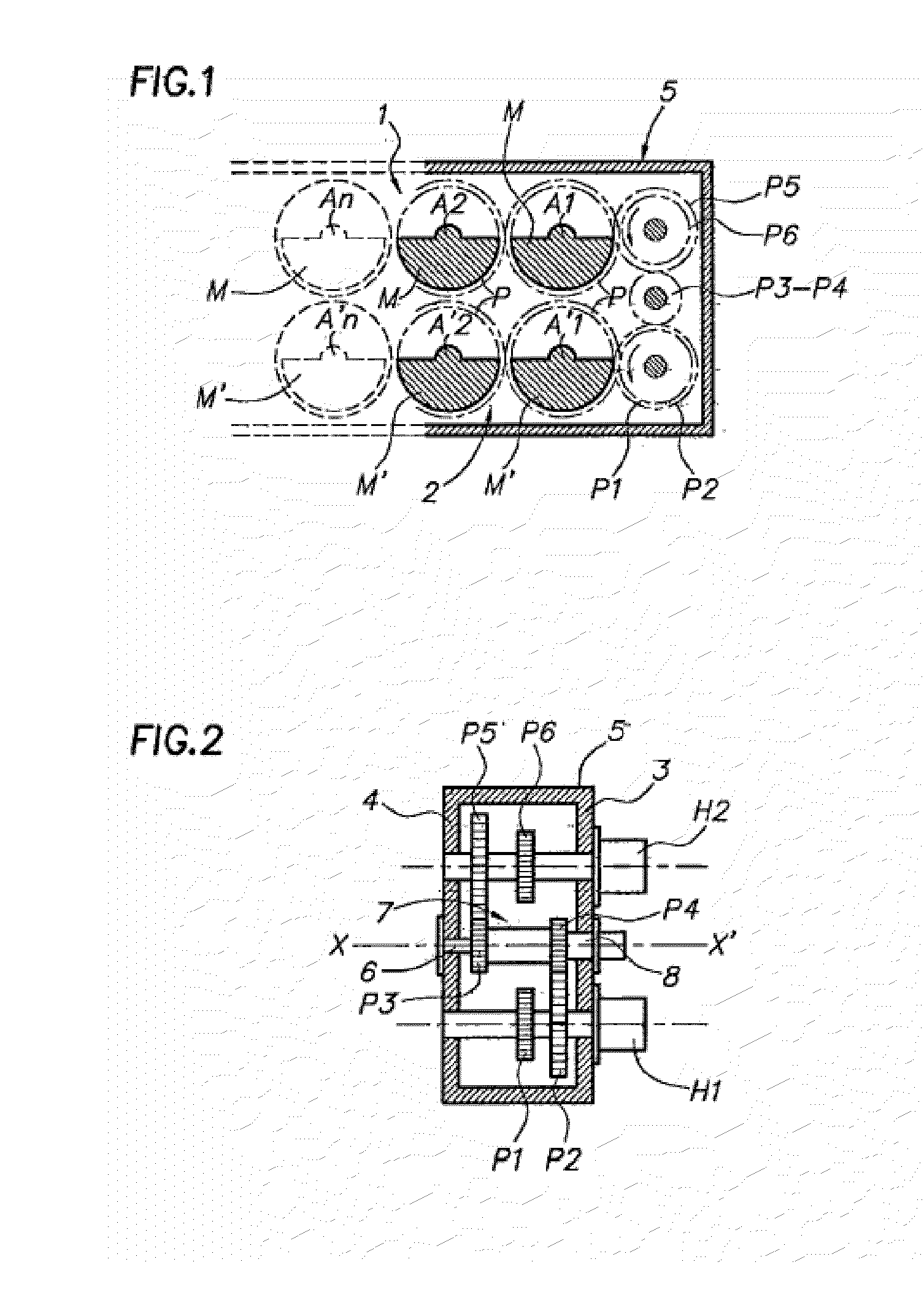
[0042]In the example illustrated in FIGS. 1 and 2 the vibrator comprises two trains 1 and 2 of off-centered flyweights rotatably mounted by means of shafts A1, A2, An-A′1, A′2, A′n, parallel to a transverse axis X, X′, and the ends of which engage into bearings borne by two parallel walls 3, 4, forming both lateral sides of a casing 5.

[0043]With each of the flyweights M, M′ is associated a cog P positioned and dimensioned so that the cogs P associated with a same train 1, 2, of flyweights M mesh with each other, by successive pairs thereof.

[0044]In FIG. 1, two trains of flyweights M are illustrated, each comprising a pair of flyweight / cog P assemblies illustrated in solid lines, the assembly partly illustrated in dashed lines indicating the implantation mode of another pair.

[0045]The driving into rotation of both trains of flyweights is ensured by means of motorization, for example comprising two hydraulic motors H1, H2, mounted on the wall 3 at one of the ends of the casing 5.

[0046...


PUM


Abstract

A vibrator with a variable moment uses a phase shifter (7) including at least two trains of flyweights each including at least two eccentric flyweights driven into rotation by two cogs which mesh with each other so as to rotate in the opposite direction relative to each other. Both trains of flyweights are coupled to each other through a remotely controllable phase shifter (7) including a first tubular drive shaft (9) interdependent in rotation at one of the its ends, with a first cog (P4) and a second central drive shaft (6) which engages into the first tubular drive shaft (9) and which is interdependent in rotation with a second cog (P3) located opposite to the first cog (P4). A tubular transmission part (8) interdependent in rotation with the first tubular drive shaft (9) ensures a diversion of the stresses exerted at the cogs (P3, P4) thereby relieving the phase shifter.

Description

BACKGROUND OF THE INVENTION[0001]1. Field of the Invention[0002]The object of the present invention is a vibrator with a variable moment using a phase shifter with reduced clearances.[0003]It relates to a vibrator with a variable moment which may notably, but not exclusively, be used for driving into the ground, objects such as stakes or pile-planks, and featuring reduced clearances.[0004]2. Description of the Prior Art[0005]Generally, it is known that the vibrators currently used in this kind of application involve at least a pair of flyweights off-centered relatively to their drive axis and means for driving into rotation both drive axes at a same speed but in an opposite direction.[0006]It is clear that by these arrangements, the centrifugal forces generated by the rotation of the flyweights are added in a direction defining a working axis and are compensated in the other directions so as to cancel out in a direction perpendicular to the working axis.[0007]It is found that for mu...

Claims


Application Information

Patent Timeline
Patent Type & Authority Applications(United States)
IPC IPC(8): F16H33/08
CPCB06B1/166Y10T74/18344E02D7/18
Inventor JEHANNO, MATHIEU
Owner PARAMETRIC TECH CORP
Why Eureka
Try Eureka