Stripping device comprising a stripping bar for a ground milling machine, stripping element for a stripping bar, and ground milling machine comprising a stripping device

a technology of stripping device and ground milling machine, which is applied in the direction of roads, roads, constructions, etc., can solve the problems of inability to unequivocally identify inability to parallel the ground or the axis of rotation, and inability to locate the position along the bottom plate edge. , to achieve the effect of preventing the slippage of at least one stripping element, reducing the number of mounting screws, and simplifying positioning

Active Publication Date: 2017-05-02
BOMAG
View PDF16 Cites 5 Cited by
  • Summary
  • Abstract
  • Description
  • Claims
  • Application Information

AI Technical Summary

Benefits of technology

[0010]One advantage of the present invention is that an assembler can interlock the form-fitting elements prior to mounting them by means of mounting screws so as to prevent slippage of the at least one stripping element during further assembly. A further advantage of the present invention is that the form-fitting elements transfer forces between the stripping bar and the stripping plate, thus relieving the mounting screws from, in particular, shearing forces.
[0011]In general, the form fit according to the present invention can prevent movement of the at least one stripping element relatively to the stripping plate in any direction, for example, transversely to the bottom plate edge of the stripping plate. It is particularly advantageous for the purpose of aiding the assembly of the at least one stripping element when the form-fitting elements are constructed so as to at least prevent slippage of the at least one stripping element along the bottom plate edge. Consequently, slippage in a direction parallel to the bottom plate edge, to the ground or to the axis of rotation is impossible. Since assembly is carried out on the bottom plate edge, an assembler can readily gage the distance between the stripping elements and the bottom plate edge, whilst in the prior art the position along the bottom plate edge is not unequivocally recognizable due to the fact that the stripping element extends only along part of this edge. The form fit simplifies positioning along the bottom plate edge.
[0012]The basic task of the mounting device is to hold the stripping element on the stripping plate. This can be achieved by a variety of different embodiments. For example, bolts, more particularly, screw-threaded bolts, can be attached to the stripping plate and / or on the respective stripping element, which bolts are guided through suitable through bores present in the respective counterpart, i.e., the stripping plate or the stripping element. Further, it is possible to use separate mounting screws, or mounting bolts, which are guided through suitable through bores present in both the stripping element and the stripping plate and secured by corresponding fastening nuts. The stripping device according to the present invention is especially useful in the case of mounting by use of mounting screws. In the case of through bores for mounting screws being present, particularly, in the stripping plate and the stripping elements, it is advantageous to have form-fitting elements formed such that an interlock of the form-fitting elements results in coaxial alignment of the through bores for the mounting screws. Thus, once the form-fitting elements interlock, the through bores for the mounting screws are aligned so as to form a continuous mounting channel into which the mounting screws can be inserted. This channel preferably extends through the at least one stripping element and the stripping plate. Once the interlock of the form-fitting elements has been established, in order to mount the at least one stripping element to the stripping plate, an assembler merely has to insert the mounting screws into the aligned through bores and fasten them.
[0013]A particularly simple method of positioning the at least one stripping element for insertion of the mounting screws is possible, when the form-fitting elements of the at least one stripping element are disposed between at least two through bores on the at least one stripping element. Stripping elements typically have at least two through bores for mounting screws, since the method of fastening with at least two screws is particularly stable. The arrangement of the form-fitting elements of the at least one stripping element in the region between these through bores may be located on all sides of the stripping element in said region. For example, the form-fitting elements may be disposed on that side with which the stripping element bears against the stripping plate in the mounted state, or on a side adjacent thereto. A possible, but less preferred, arrangement might also be for the form-fitting elements to be disposed in the mounted state on that side of the at least one stripping element that faces away from the stripping plate. It is also conceivable for the form-fitting elements to be positioned on the edge between two sides of the stripping element. What is important is that the form-fitting elements be positioned in that region that is delimited by at least two through bores. Such an arrangement is particularly suitable for the transmission of forces between the stripping element and the stripping plate and hence particularly stable.
[0014]It is further helpful when the stripping plate has a mounting recess for accommodation of the at least one stripping element so as to improve force transmission. It is preferable in this regard for the form-fitting elements to be disposed in the mounting recess. The mounting recess provides a step in the stripping plate, which step serves as a means of attachment for the at least one stripping element. Thus, the mounting recess is substantially a thinner portion of the stripper plate, located near the lower edge of the plate. This thinner portion corresponds to an abutment tongue forming an extension of the stripper plate. The transition to the normal-sized region of the stripping plate is formed by a step or knee, on which the at least one stripping element can be mounted. Due to the mounting on the step, forces can be transferred from the stripping element to the stripping plate in a particularly effective manner.
[0015]To prevent wedging or other malfunctions due to the vertical adjustment of the stripping device or deposition of milled material, the at least one stripping element is accommodated in the mounting recess so as to be flush with the stripping plate. No part protrudes from the mounting recess beyond the normal-sized region of the stripping plate. The stripping element as well as the mounting screws and the form-fitting elements are accommodated so as to be fully flush with the mounting recess. An assembler can also see that the form-fit between all parts has been accomplished without any errors by inspecting the flush contact. If the form-fitting elements are not brought to a proper interlock, a flush accommodation of the stripping element in the mounting recess is not possible.

Problems solved by technology

Consequently, slippage in a direction parallel to the bottom plate edge, to the ground or to the axis of rotation is impossible.
Since assembly is carried out on the bottom plate edge, an assembler can readily gage the distance between the stripping elements and the bottom plate edge, whilst in the prior art the position along the bottom plate edge is not unequivocally recognizable due to the fact that the stripping element extends only along part of this edge.

Method used


Image

  • Stripping device comprising a stripping bar for a ground milling machine, stripping element for a stripping bar, and ground milling machine comprising a stripping device
  • Stripping device comprising a stripping bar for a ground milling machine, stripping element for a stripping bar, and ground milling machine comprising a stripping device
  • Stripping device comprising a stripping bar for a ground milling machine, stripping element for a stripping bar, and ground milling machine comprising a stripping device

Examples


Embodiment Construction

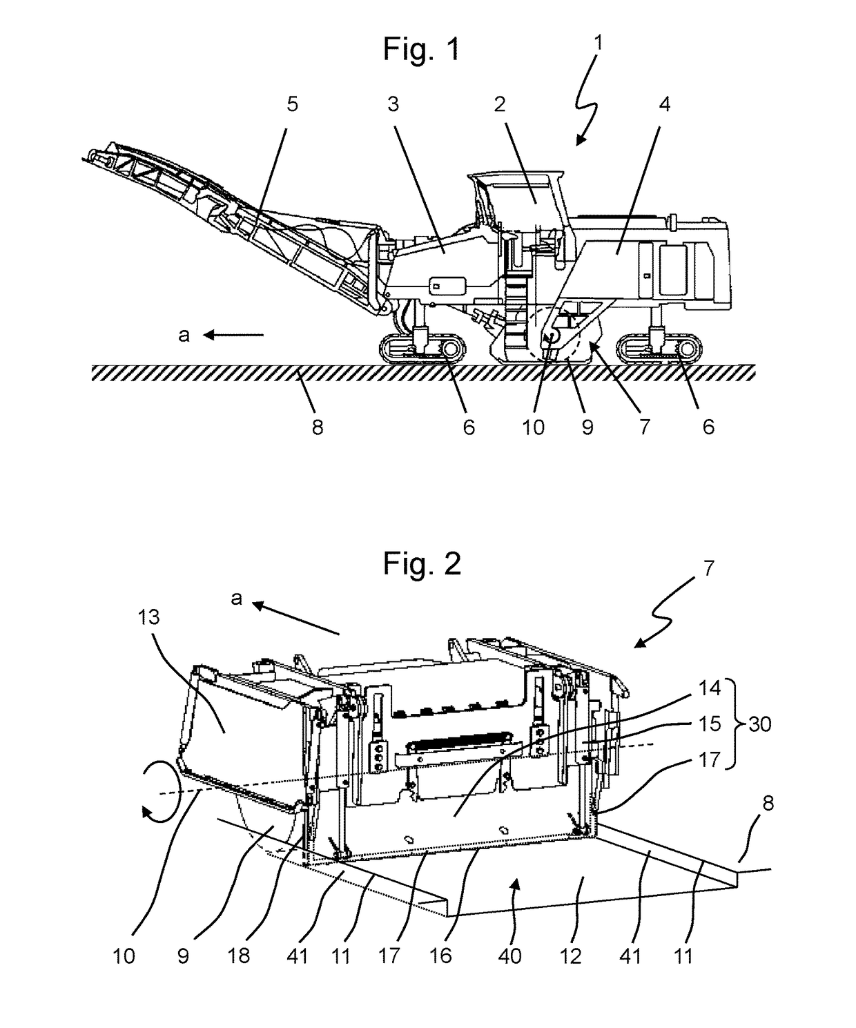
[0030]FIG. 1 shows a generic ground milling machine 1, in this case a road milling machine or cold milling machine equipped with a central drum. It comprises a machine frame 3, an operator's platform 2, a drive engine 4 and crawler tracks 6. By means of a milling drum 9 mounted in the milling drum box 7 for rotation about the axis of rotation 10, the ground milling machine 1 mills, in operational mode, the ground 8, which is depleted in the direction of advance “a”. By way of the discharge conveyor 5, the milled material is transferred to a transport vehicle (not shown) and dispatched.

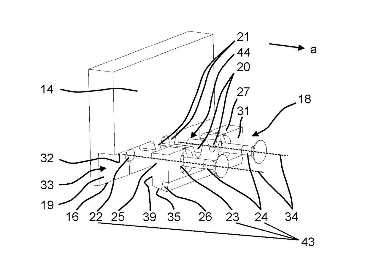
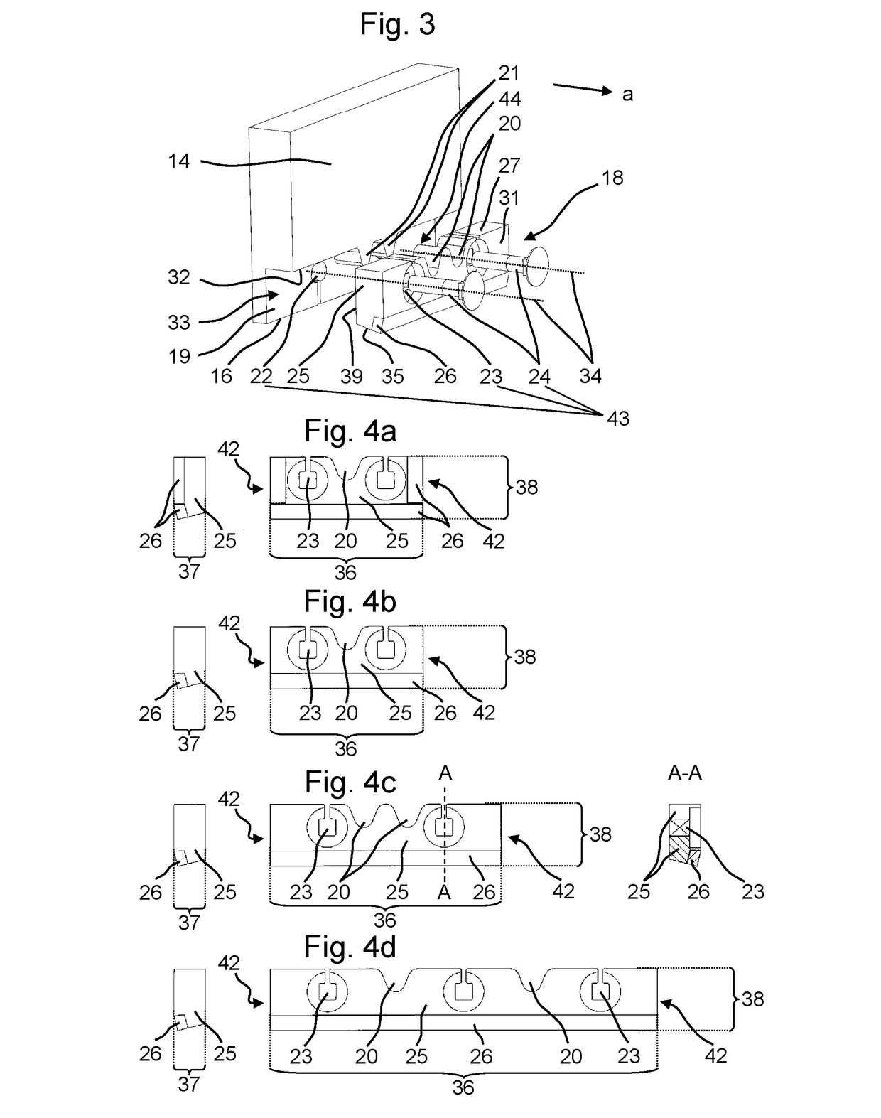
[0031]The structure and function of the milling drum box 7 is illustrated in FIG. 2. The milling drum box 7 is delimited at the sides by the side plates 13, which are intersected by the axis of rotation 10 of the milling drum 9. The side at the rear, as regarded in the direction of advance “a”, is essentially formed by a stripping device 30, which comprises a stripping plate 14, a height adjustment dev...


PUM


Abstract

The present invention relates to a stripping device for a ground milling machine, comprising a stripping plate comprising a bottom plate edge and a stripping bar comprising at least one stripping element disposed on the bottom plate edge, wherein form-fitting elements are present on the at least one stripping element and on the stripping plate, which form-fitting elements at least partially interlock in complementary fashion and prevent displacement of the at least one stripping element. The present invention further relates to a stripping element for such a stripping device, and to a ground milling machine having such a stripping device.

Description

CROSS-REFERENCE TO RELATED APPLICATIONS[0001]The present application claims priority under 35 U.S.C. §119 of German Patent Application No. 10 2013 009 611.1, filed Jun. 7, 2013, the disclosure of which is hereby incorporated herein by reference in its entirety.FIELD OF THE INVENTION[0002]The present invention relates to a stripping device comprising a stripping bar for a ground milling machine, to a stripping element for such a stripping bar, and to a construction vehicle, more particularly, a ground milling machine, comprising such a stripping device.BACKGROUND OF THE INVENTION[0003]Generic construction vehicles, more particularly, ground milling machines such as road milling machines, recyclers, stabilizers, or surface miners, are frequently used in road and path construction. They comprise a machine frame, an operator's platform, a plurality of crawler tracks, and a drive engine, usually of the Diesel type. The key element of such a ground milling machine is a milling drum mounte...

Claims


Application Information

Patent Timeline
Patent Type & Authority Patents(United States)
IPC IPC(8): E01C23/088E01C23/12
CPCE01C23/088E01C23/127
Inventor LOSEN, FABIANSCHAEFER, MARKUSWACHSMANN, STEFFEN
Owner BOMAG
Why Eureka
Try Eureka