Separator Construction of a Fluidized Bed Boiler

a technology of separator and fluidized bed, which is applied in the direction of steam boiler components, combustion process, combustion treatment, etc., can solve the problems of not being able to support the separator directly, the number of problems has increased, and it is no longer possible to support the separator to the primary steel structure, and achieves the effect of saving construction costs and less weigh

Active Publication Date: 2010-02-04
FOSTER WHEELER ENERGIA OY
View PDF8 Cites 12 Cited by
  • Summary
  • Abstract
  • Description
  • Claims
  • Application Information

AI Technical Summary

Benefits of technology

[0022]the supporting steel structures and foundations of the separator and the boiler can be designed for less weight, whereby savings are gained in constructions costs, too.

Problems solved by technology

As for their strength, such water / steam tube walls are, in view of their size, relatively weak, so they cannot be used to bear directly the stresses caused by the weight of the boiler or of the components thereof, the pressure of the combustion space or thermal expansion, perhaps notwithstanding the direction of the tubes, but, for example, different beam structures are used to support the boiler and different structural parts thereof.
However, with the increase in the size of the power boilers and, at the same time, of the separators, and with the change in their shape, a number of problems have arisen.
With this shape, especially with large separators, it is no longer possible to support the separator to the primary steel structure, nor to the bottom of the flue gas channel.
When supporting the separator directly to the primary steel structure, the problem will be that there are a number of walls that are in angular position relative to the primary steel structure, lacking a beam above in the primary steel structure, and thus, a place where to hang the separator.
It has been noted, however, that large, not right-angled separators do not have enough load carrying areas (lines) between the circumference of the separator and the wall line of the flue gas channel.
In practice, this means that, for example, one third or one fourth of the circumferential length of the separator (depending on whether the separator is hexagonal or octagonal) supports the weight of the whole separator and the sand and ash therein, which, in turn, leads to too heavy of local stresses.
It has been noted that one of the problems with this arrangement is that the maximum width of the flue gas channel with the present separator supporting methods may be equal to the diameter of the separator.
In some arrangements, even a smaller width of the flue gas channel has been used, but it has proved especially problematic, because a fact is that the cross section of the flue gas channel has to be large enough, so that the flue gases can flow without any substantial pressure loss in the heat recovery section.
This, however, instantly increases the total height of the building.
The same problem is to be seen in cases where the width of the flue gas channel is limited to the diameter of the separator, especially, when talking about large boilers, whereby there are a lot of separators on both sides of the furnace.
Thirdly, it has been impossible to define the weight of the separator, and also the weight of sand and ash therein, when using the constructions in accordance with the prior art, by measuring, because there have always been a large number of hanger rods.
An additional problem related to a large number of hanger rods is that it has been, in practice, very difficult, if not impossible, to arrange the supporting of the separator in such a way that all hanger rods are subject to the same load.

Method used


Image

  • Separator Construction of a Fluidized Bed Boiler
  • Separator Construction of a Fluidized Bed Boiler
  • Separator Construction of a Fluidized Bed Boiler

Examples


Embodiment Construction

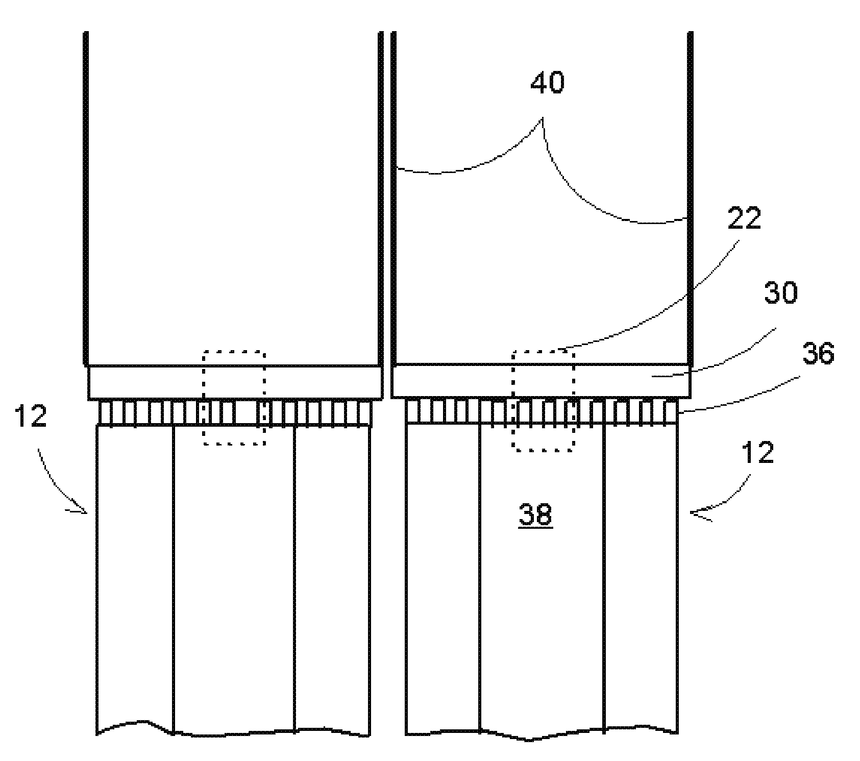
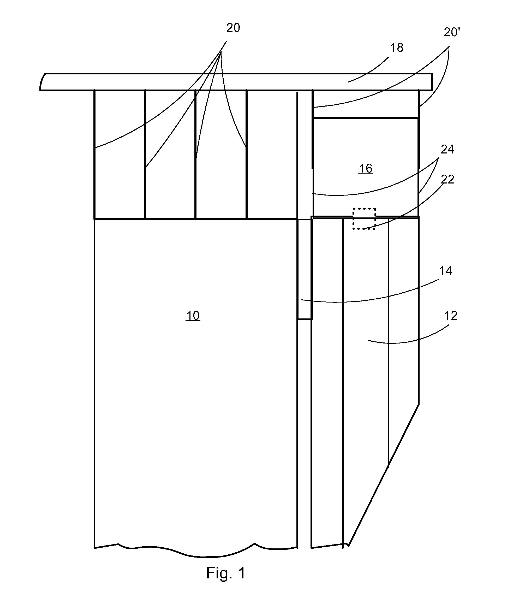
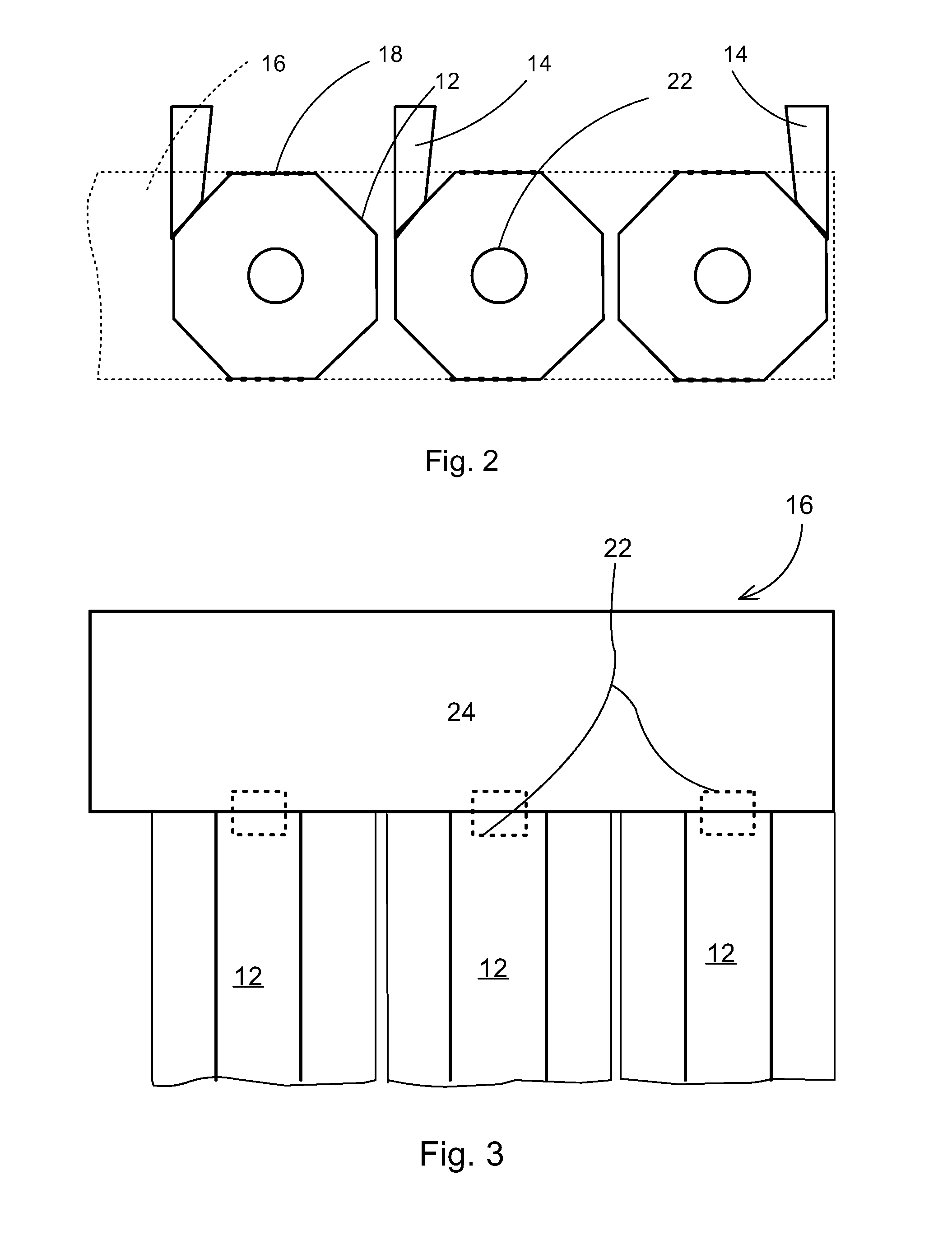
[0029]A fluidized bed boiler in accordance with the prior art disclosed in FIG. 1, as a partially sectional view, comprises, as for the parts illustrated in the drawing, a furnace 10, one or more separators 12 located on one side or both sides of the furnace 10, a flue gas conduit 14 connecting them, a flue gas channel 16 located above the separator / separators 12 and a supporting structure 18, i.e., a so-called primary steel structure located in the upper part of the building housing the boiler. Both the furnace 10 and the flue gas channel 16 are suspended with hanger rods or wires 20 from the supporting structure 18. Furthermore, the figure also illustrates a conduit 22 preferably located at the centerline of the separator 12 and leading from the separator 12 to the flue gas channel 16, from which conduit 22 the flue gases, having the solid material separated therefrom in the separator 12, rise to the flue gas channel 16. In the arrangement in accordance with the prior art illustra...


PUM


Abstract

A separator construction, connectable to a fluidized bed boiler having a furnace, for circulating bed material and returning the material to the furnace. The separator construction includes walls, a ceiling, an inlet conduit, an outlet conduit in flow communication with a flue gas channel located above the separator, and a suspending device connecting the separator to a supporting structure in a building housing the boiler. The suspending device is formed of a frame arranged between the flue gas channel and the separator in connection with an upper circumference of the wall of the separator, and hanger rods or wires connecting the frame directly to the supporting structure.

Description

[0001]This application is a U.S. national stage application of PCT International Application No. PCT / FI2007 / 050280, filed May 16, 2007, and published as PCT Publication No. WO 2007 / 135238 A2, and which claims priority from Finnish patent application number 20060492, filed May 19, 2006.FIELD OF THE INVENTION[0002]The present invention relates to a separator construction of a fluidized bed boiler, such as one utilized for generating power. The invention has application to a fluidized bed boiler, generally comprising an actual furnace, and apparatuses for treating flue gases, as well as apparatuses for circulating the bed material and returning the material to the furnace. The invention especially relates to suspending of the separator to be used in connection with such a boiler for generating power.BACKGROUND OF THE INVENTION[0003]The fluidized bed boilers related to the present invention and, more accurately, the components thereof, are equipped with so-called water / steam tube walls,...

Claims


Application Information

Patent Timeline
Patent Type & Authority Applications(United States)
IPC IPC(8): F23C10/08F22B37/24B01J8/18
CPCF22B31/0007F23C10/10F22B37/244B01J8/00F22B31/00F22B37/24F23C10/18
Inventor LANKINEN, PENTTI
Owner FOSTER WHEELER ENERGIA OY
Why Eureka
Try Eureka