
Sag-free retractable awning

a retractable awning and awning technology, applied in the field of retractable awnings, can solve the problems of inconvenience for the user of the awning, damage to the awning,

Inactive Publication Date: 2010-02-04
CAREFREESCOTT FETZER
View PDF20 Cites 20 Cited by
  • Summary
  • Abstract
  • Description
  • Claims
  • Application Information

AI Technical Summary

Benefits of technology

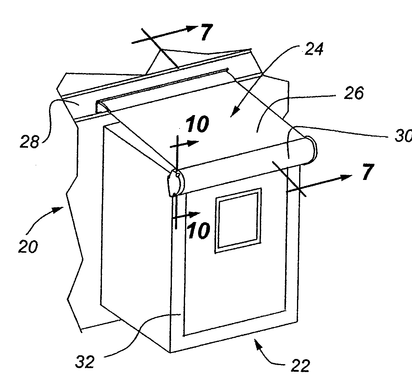
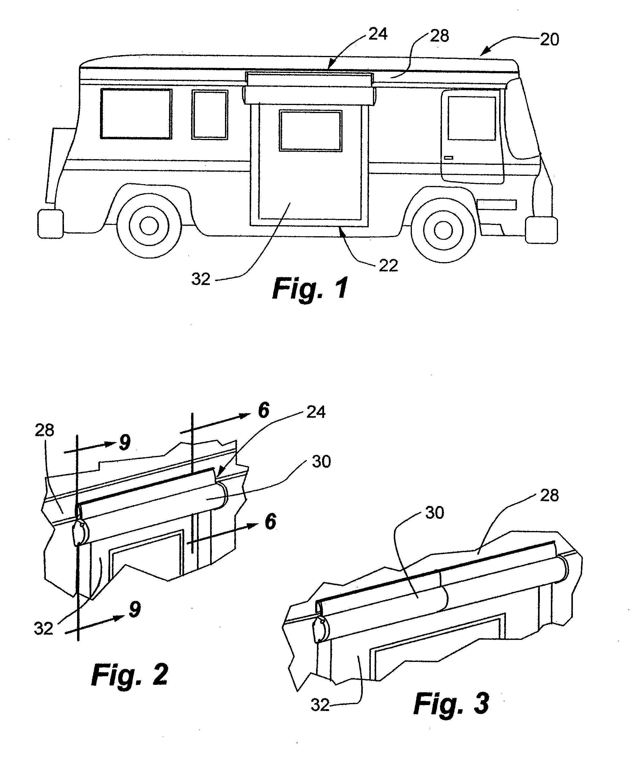
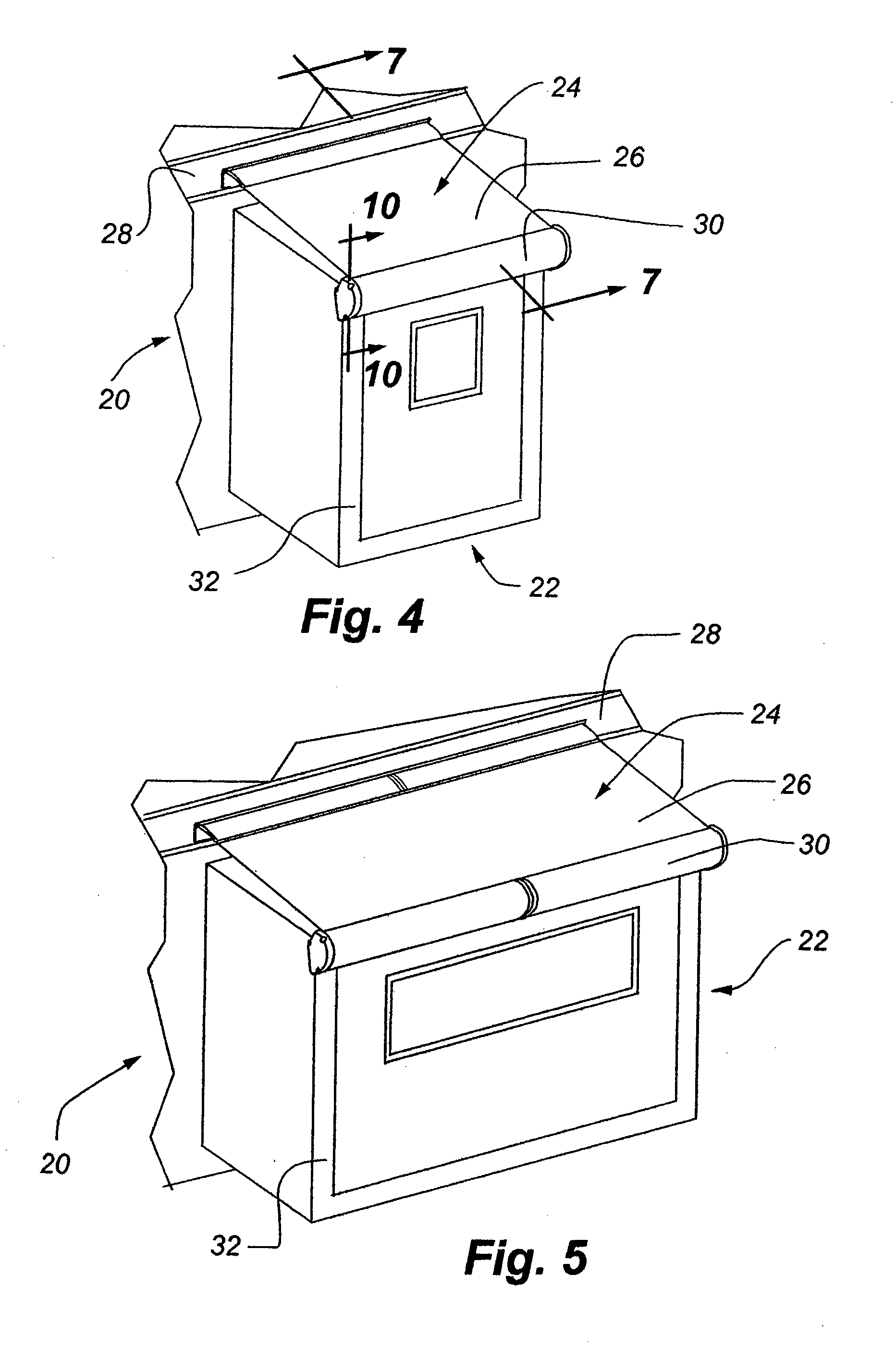
[0007]While the present invention is disclosed in different embodiments with an embodiment showing a roll bar for a retractable awning that is rotatably mounted on a support surface and other embodiments showing a roll bar mounted to be extended away from the support surface, the roll bars are rotatably mounted between end caps where the ends of the rollers are supported. The roll bar has attached thereto one edge of an awning sheet or canopy while the other edge of the awning sheet or canopy is connected to the support surface or a lead bar extendable away from the support surface depending upon whether or not the roll bar is mounted on the support surface or is part of the lead bar. A conventional coil spring is positioned within the roll bar so as to be tensioned as the roller is rotated to unwrap the awning sheet therefrom whereby the tension in the coil spring will assist in retracting the awning while wrapping the awning sheet around the roll bar. The coil spring therefore maintains a tension in the awning sheet and also a pulling force on the roll bar regardless of the position of the roll bar in a fully extended or retracted condition inasmuch as even in the retracted condition when the spring is least tensioned, it has a pre-tension placed thereon.

Problems solved by technology

When the awning roller sags, the awning fabric, if it is extended, will form a depression which will undesirably accumulate rain water, which could cause damage to the awning and certainly an inconvenience to the user of the awning.

Method used


Image

  • Sag-free retractable awning
  • Sag-free retractable awning
  • Sag-free retractable awning

Examples


second embodiment

[0055]the present invention is shown in FIGS. 15-18. In this embodiment, the awning system is incorporated within a box-type housing of the general type shown in U.S. Pat. No. 7,188,889 issued Mar. 13, 2007, which is of common ownership with the present application and the disclosure of which is hereby incorporated by reference. The box awning 192 shown in FIGS. 15-18 is not necessarily mounted on a slide-out unit but simply on any horizontal or vertical surface with the awning disclosed in FIGS. 15-18 being shown mounted on a horizontal surface 194. FIG. 15 shows the awning fully retracted and housed within a housing 196 with FIG. 16 showing the housing being open so that a lead bar 198, which is secured to the outer edge of the awning canopy 200, can be extended away from the housing with sets of pivotal support arms 202 that also support a longitudinally extending transverse support bar 204 to help prevent the awning canopy from sagging. The support arms conventionally include sp...

embodiment 220

[0056]An alternative embodiment 220, and possibly the preferred embodiment of the operating system, which would obtain the same results as shown in the embodiment of FIGS. 1-14, is shown in FIGS. 19 and 20. In this embodiment, the end caps 48 would be identical as would their connection to a roll bar 222 even though the roll bar has been modified slightly so as to include two sets of diametrically opposed elongated C-groove connectors 224 with each of the four defined connectors being equally spaced around the circumference of the roll bar for a purpose to be described hereafter.

[0057]A revised collar 226 for insertion into an associated open end of the roll bar for attachment thereto can be seen to include a circular plate 228 having radiating circumferentially spaced webs 230 adapted to fit snuggly against the interior wall of the roll bar to center the collar within the associated open end of the roll bar. A cylindrical body 232 passes through the center of the collar with the bo...


PUM


Abstract

A retractable awning having one edge of an awning canopy fixed and a movable opposite edge with the opposite edge being secured to a rotatable roll bar includes a floating mounting for the roll bar so that a bias on the roll bar urging the roll bar to rotate toward a retracted position of the awning permits the wrapped fabric on the roll bar to remain in engagement with an engagement wall of a mounting chassis so that the roll bar is prevented from sagging along its length regardless of the number of wraps of fabric about the roll bar.

Description

BACKGROUND OF THE INVENTION[0001]1. Field of the Invention[0002]A retractable awning includes a roller about which an awning canopy can be wrapped and unwrapped with the roller mounted in a housing so as to be floating whereby tension placed on the canopy pulls the awning roller against a fixed surface along the entire length of the roller to prevent sagging of the roller.[0003]2. Description of the Relevant Art[0004]Retractable awnings have been commonly used for many years with some being manually driven between extended and retracted positions and others electrically driven between the same positions. Awnings have been used as coverings for doorways, windows, and in more recent years on the sides of recreational vehicles, motor homes, and the like. Some such recreational vehicles and motor homes include a slide-out unit which is a box-like structure, which can be selectively extended from the side of the vehicle to increase useful space within the vehicle when the vehicle is park...

Claims


Application Information

Patent Timeline
Patent Type & Authority Applications(United States)
IPC IPC(8): E04F10/06
CPCE04F10/06B60P3/343
Inventor THOMPSON, SCOTT P.WAGNER, ROBERT
Owner CAREFREESCOTT FETZER
Learn More