

Fuel engine servo loading device and optimal efficiency operating control method thereof
- Summary
- Abstract
- Description
- Claims
- Application Information
AI Technical Summary
Benefits of technology
Problems solved by technology
Method used
Image

Examples
Embodiment Construction
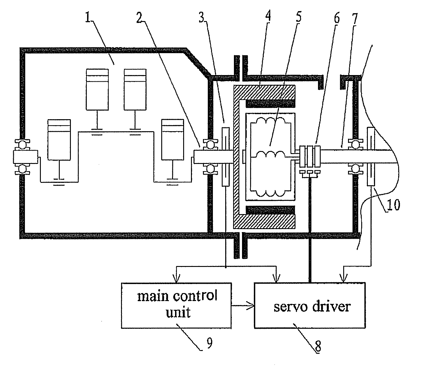
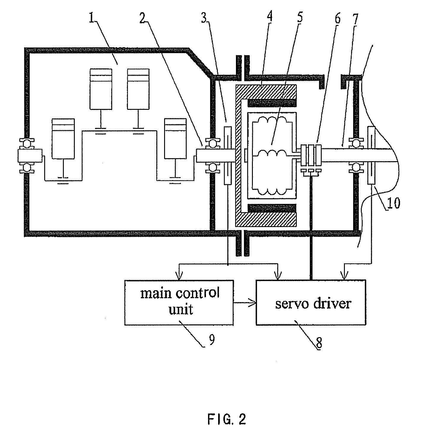
[0021]The structure of a servo loading device of the fuel engine according to an embodiment of the invention is shown in FIG. 2, the machine of the embodiment is three-phase permanent magnet synchronous electric machine. A fuel engine 1 is connected to the servo loading device comprising a permanent magnet synchronous machine, a servo driver and a main control unit. A first rotor 4 of the machine is directly connected with an output shaft 2 of the fuel engine 1. The first rotor 4 of the machine is embedded with permanent magnetic material, with a second rotor 5 therein. The second rotor 5 is a winding wound around an iron core, and the shaft of the second rotor 5 is the output shaft 7 of this device. A speed / position sensor 3 which is connected with a main control unit 9 and a servo driver 8 is provided on the first rotor 4 of the machine. A position sensor 10 which is connected with the torque servo driver 8 is provided on the output shaft 7 of this device. The main control unit 9 ...
PUM
 Abstract
Description
Claims
Application Information