Liquid Droplet Jetting Apparatus

Active Publication Date: 2010-02-04
BROTHER KOGYO KK
View PDF5 Cites 9 Cited by
  • Summary
  • Abstract
  • Description
  • Claims
  • Application Information

AI Technical Summary

Benefits of technology

[0018]On the other hand, when the degree of thickening of liquid in the nozzle is extreme, and it is difficult to discharge the thickened liquid inside the nozzle only by carrying out the liquid purge, the second purge mode which is specialized for the discharge of the thickened liquid is selected. In this case, the second air discharge purge is carried out so as to destroy the meniscus of the liquid thickened inside the nozzle. For example, the meniscus of the liquid thickened inside the nozzle is destroyed by carrying out a strong

Problems solved by technology

However, in a case that the thickening of the ink in the nozzle is extreme (severe) due to a such reason that a state that the power supply of the printer is OFF has continued for a long period

Method used


Image

  • Liquid Droplet Jetting Apparatus
  • Liquid Droplet Jetting Apparatus
  • Liquid Droplet Jetting Apparatus

Examples


first modification

[0087]In the embodiment, as an example of selecting one of the first purge mode and the second purge mode, switching according to the period of time for which the power supply had been switched off is cited. However, the method for selecting the purge mode is not restricted to the switching according to the time for which the power supply had been switched off.

[0088]For example, a purge command may be input by the user who has ascertained upon looking an image recorded practically, that a printing quality has degraded. In other words, when a purge command is input to the control unit 8 from an external input unit (external input device) such as a PC connected to the printer 1, or from an operation panel of the printer 1, the maintenance control section 82 may carry out the switching of the purge mode depending on whether or not the command has been input repeatedly during a predetermined time. In other words, when a frequency of input n of inputting the purge command from an outside...

second modification

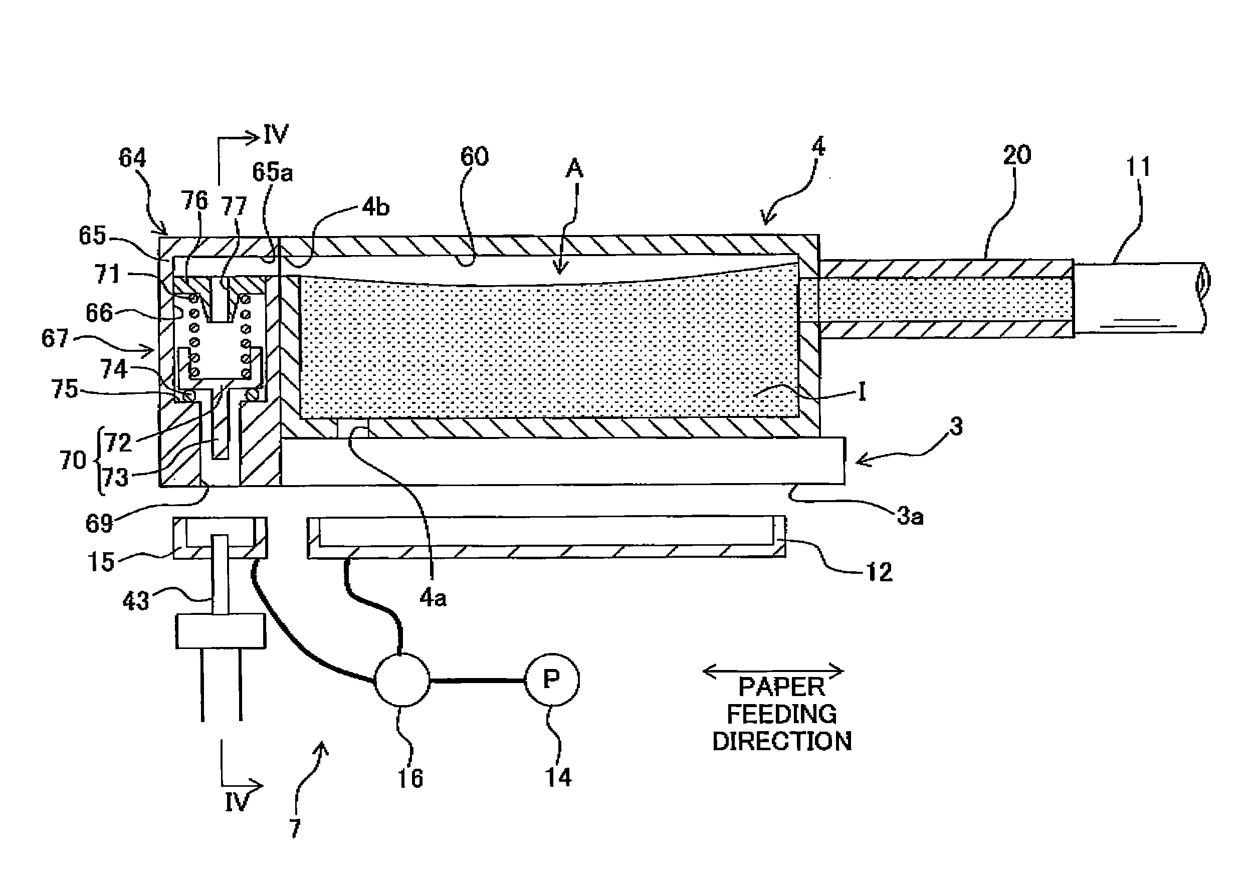
[0095]The high-speed suction carried out in the second purge mode which is selected when the degree of thickening of the ink inside the nozzle 40 is extreme (refer to FIG. 8A), is only aimed at destroying the meniscus in the nozzle 40 by reducing rapidly the pressure inside the ink storage chamber 60. When only this object is to be achieved, it is not necessary to make the suction time that long, and the suction operation in which the suction speed (suction force) is high is to be carried out only for a short time. However, in such high-speed suction with such a short suction time, an amount of air (gas) which is discharged from the air discharge channel 66 is small. Therefore, when the thickening of the ink inside the nozzle 40 is extreme and also mixing (entry) of air into the ink storage chamber 60 is substantial, sometimes it is not possible to discharge sufficiently the air inside the ink storage chamber 60 only by carrying out the second purge mode which includes the two stage...

third modification

[0098]One suction pump 14 is not necessarily required to carry out both the suction discharge of the ink from the nozzle 40, and the suction discharge of the air from the air discharge channel 66. Separate suction pumps may carry out the suction from the nozzle 40, and the suction from the air discharge channel 66. Moreover, the discharge of the ink from the nozzle 40 is not restricted to the suction by the suction pump. In other words, a pressurizing pump (a purge mechanism) may be connected to the ink supply channel including the ink storage chamber 60 and the tube 11, and the ink may be ejected from (through) the nozzle by pressurizing the ink inside the ink supply channel by this pump.


PUM


Abstract

A liquid droplet jetting apparatus is capable of carrying out selectively a first purge mode and a second purge mode. In the first purge mode, a first air discharge purge of discharging air in an ink storage chamber is carried out while maintaining a meniscus of the ink. In the second purge mode, a second air discharge purge of discharging air inside the ink storage chamber is carried out while destroying the meniscus of the ink. Accordingly, there is provided a liquid droplet jetting apparatus in which it is possible to discharge a gas inside a liquid supply channel from an upstream side of the nozzle, and also, when the degree of thickening of the liquid inside the nozzle is extreme, it is possible to discharge the thickened liquid assuredly from the nozzle.

Description

CROSS REFERENCE TO RELATED APPLICATION[0001]The present application claims priority from Japanese Patent Application No. 2008-197686, filed on Jul. 31, 2008, the disclosure of which are incorporated herein by reference in their entirety.BACKGROUND OF THE INVENTION[0002]1. Field of the Invention[0003]The present invention relates to a liquid droplet jetting apparatus which jets liquid droplets of a liquid.[0004]2. Description of the Related Art[0005]As a liquid droplet jetting apparatus which jets liquid droplets from nozzles, an ink-jet printer which includes an ink-jet head which jets droplets of an ink onto a recording paper has hitherto been known. In such an ink-jet printer, due to entry of an air bubble into an ink channel or due to increase in the viscosity (due to thickening) of the ink inside the nozzle caused by the drying of the ink, nozzle jetting failure occurs in some cases. To address this situation, an ink-jet recording apparatus of general type is provided with a uni...

Claims


Application Information

Patent Timeline
IPC IPC(8): B41J2/165
CPCB41J2/16532
Inventor NISHIDA, KATSUNORI
Owner BROTHER KOGYO KK
Why Eureka
Try Eureka