3D image projection system

a projection system and image technology, applied in the field of 3d image projection system, can solve the problems of high cost of system which requires multiple projectors to achieve 3d image projection, and the viewer does not perceive the side depth view

Inactive Publication Date: 2010-02-04
THOMSON LICENSING SA
View PDF12 Cites 4 Cited by
  • Summary
  • Abstract
  • Description
  • Claims
  • Application Information

AI Technical Summary

Problems solved by technology

A problem with the above described methods of projecting a 3D image is that the viewer does not perceive the side depth view when the viewer moves his head around with respect to the projected image.
While the system above is able to create a 3D image viewable in substantially full depth from a variety of view points, a system which requires multiple projectors to accomplish 3D image projection can be very costly and may have difficult issues with proper alignment and / or calibration between the multiple projectors.

Method used


Image

  • 3D image projection system
  • 3D image projection system

Examples


Embodiment Construction

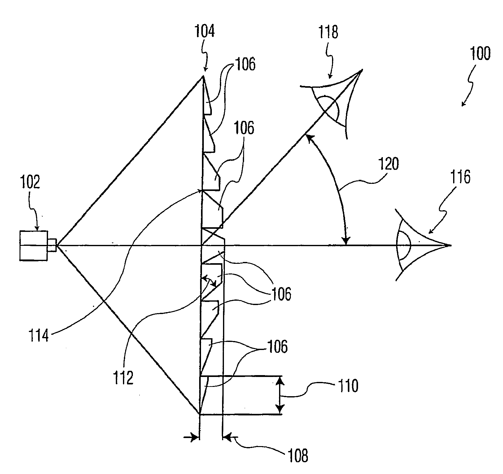
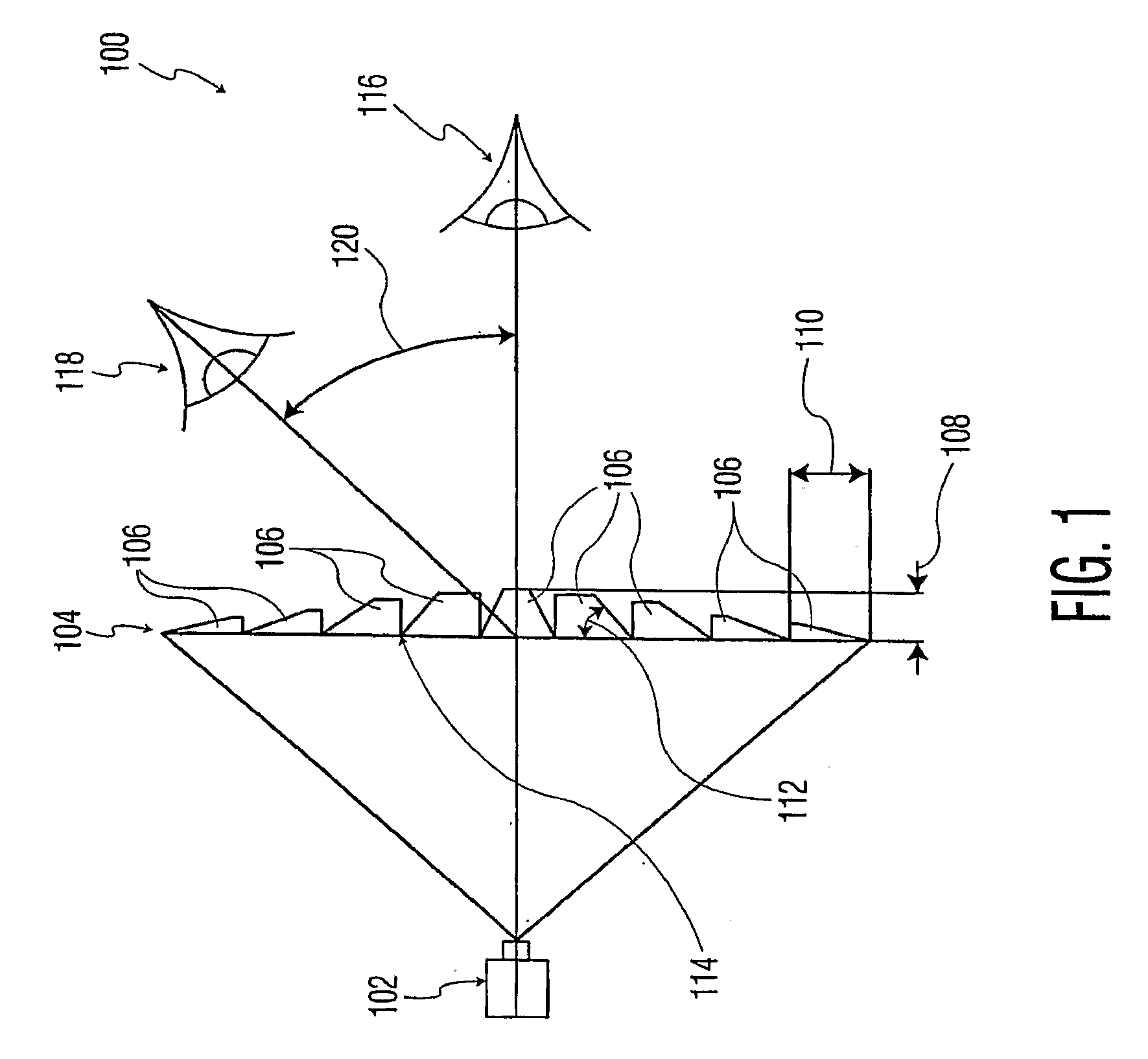
[0008]Referring now to FIG. 1 in the drawings, a 3D image projection system according the present invention is illustrated. 3D image projection system 100 comprises a projector 102 and a display screen 104. Projector 102 is configured to project images onto screen 104 at very high refresh rates, with faster rates being better. To achieve a good 3D image result, projector 102 should display images at a refresh rate of 24 times faster than the typical refresh rate used by currently available imagers of multi-projector 3D image projection systems so as to provide two or more view images per typical frame rate (30 frames per second). In other words, projector 102 is capable of an image refresh rate of at least about 60 frames per second. The purpose of having such high refresh rates is to provide the same amount of image data to the screen 104 as a multi-projector system, but without the need for more than a single projector. As such, the 3D image projection system according to the inve...


PUM


Abstract

A 3D image projection system has a display screen having an array of pixels, an array of pixel pyramids associated with the array of pixels, and a projector configured to project light onto the display screen.

Description

FIELD OF THE INVENTION[0001]The invention relates generally to the display of 3D images. More specifically, the invention relates to 3D image projection systems.BACKGROUND OF THE INVENTION[0002]It is well known that a projected image may be enhanced with an appearance of depth by converting the projected image into a so-called 3D image. This is most often accomplished by optically polarizing the images which are to be viewed by a viewer's left eye differently than the images which are to be viewed by a viewer's right eye. The 3D effect is perceived by the viewer when the viewer views the polarized images though the use of polarized filter lenses, commonly configured as ‘3D viewing glasses’ with a polarized filter for use with the left eye of the viewer and a differently polarized filter for use with the right eye of the viewer. When the 3D viewing glasses are used to view the 3D images, the left eye of the viewer sees only the light polarized appropriately for passage through the po...

Claims


Application Information

Patent Timeline
Patent Type & Authority Applications(United States)
IPC IPC(8): H04N9/31G03B21/00H04N13/363
CPCH04N13/0459H04N13/363
Inventor YOON, YOUNGSHIK
Owner THOMSON LICENSING SA
Why Eureka
Try Eureka