Display system for work vehicle and generation method

a technology for generating methods and work vehicles, which is applied in soil-shifting machines/dredgers, instruments, transportation and packaging, etc., can solve the problems of difficult to understand the actual shape of the surrounding environment of the work vehicle from the bird's-eye view image, and not easy to see that the ground is inclined or uneven

Active Publication Date: 2021-07-15
THE UNIV OF TOKYO +1
View PDF0 Cites 3 Cited by
  • Summary
  • Abstract
  • Description
  • Claims
  • Application Information

AI Technical Summary

Benefits of technology

[0010]According to the present invention, a display image can be generated in which the shape of the surrounding environment of a work vehicle can be understood easily.

Problems solved by technology

As a result, it is difficult to understand the actual shape of the surrounding environment of the work vehicle from the bird's-eye view image.
Consequently, it is not easy to see that the ground is inclined or uneven from the bird's-eye view image.

Method used


Image

  • Display system for work vehicle and generation method
  • Display system for work vehicle and generation method
  • Display system for work vehicle and generation method

Examples


first embodiment

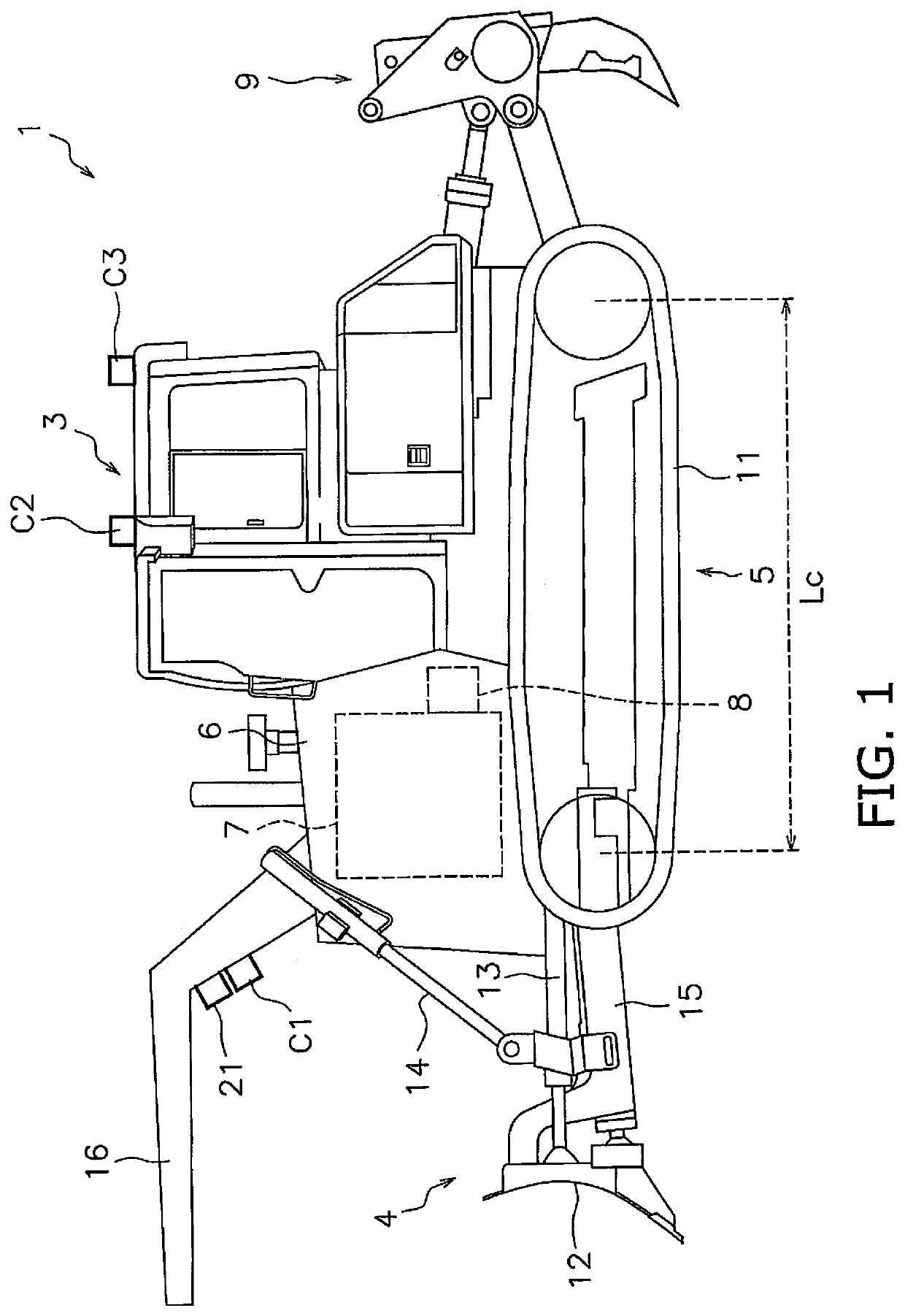
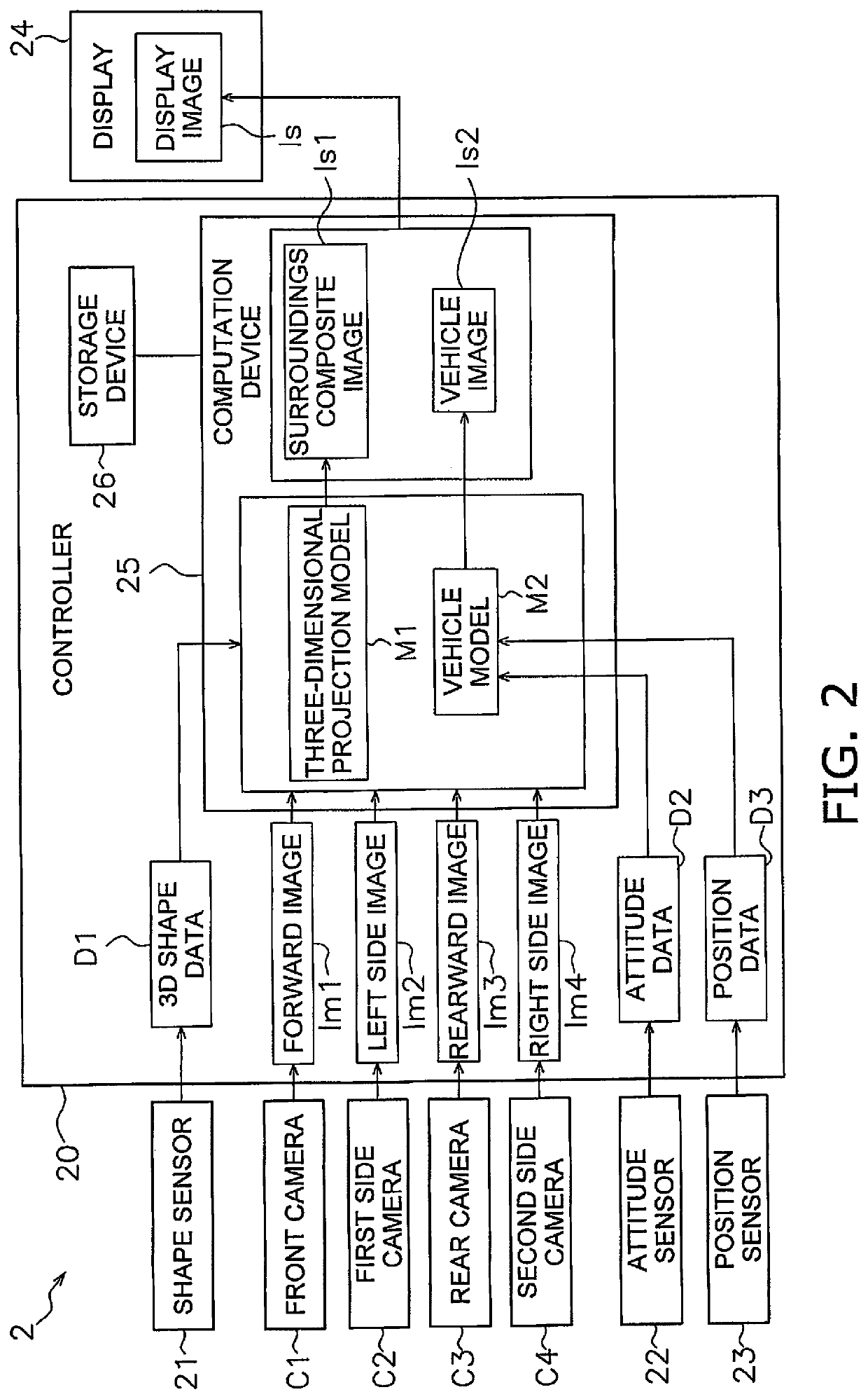
[0026]FIG. 2 is a block diagram illustrating a configuration of a display system 2 and a processing flow of the display system 2 according to a As illustrated in FIG. 2, the display system 20 includes a plurality of cameras C1 to C4. The plurality of cameras C1 to C4 are attached to the vehicle body 3. The plurality of cameras C1 to C4 are fish-eye lens cameras. The angle of view of each of the plurality of cameras C1 to C4 is 180 degrees. However, the angle of view of each of the plurality of cameras C1 to C4 may be less than 180 degrees. Alternatively, the angle of view of each of the plurality of cameras C1 to C4 may be more than 180 degrees. The plurality of cameras C1 to C4 includes a front camera C1, a first side camera C2, rear camera C3, and a second side camera C4.

[0027]As Illustrated in FIG. 1, the front camera C1 is attached to a front portion of the vehicle body 3. Specifically, the vehicle body 3 includes a front camera support portion 16 as illustrated in FIG. 1. The ...

second embodiment

[0073]FIG. 9 illustrates an example of the display image Is according to the In the display image Is illustrated in FIG. 9, a sharp downward slope Sp2 is present to the right of the work vehicle 1. A sharp upward slope Sp3 is present to the left of the work vehicle 1.

[0074]The controller 20 determines that the region Sp1 in front of the work vehicle 1 is a first level region. In addition, the controller 20 determines that the sharp downward slope Sp2 to the right and the sharp upward slope Sp3 to the left are second level regions. The controller 20 portrays the sharp downward slope Sp2 to the right and the sharp upward slope Sp3 to the left with a color different from the front region Sp1 in the display image Is.

[0075]In the display system 2 according to the second embodiment explained above, the controller 20 evaluates a plurality of regions included in the surrounding environment based on the 3D shape data D1, and displays the second level regions and the first level regions in d...


PUM


Abstract

The camera captures an image of a surrounding environment of a work vehicle and outputs image data indicative of the image. The shape sensor measures a three-dimensional shape of the surrounding environment and outputs 3D shape data indicative of the three-dimensional shape. A controller acquires the image data and the 3D shape data. The controller generates a three-dimensional projection model based on the 3D shape data. The three-dimensional projection model portrays the three-dimensional shape of the surrounding environment. The image is projected onto the three-dimensional projection model based on the image data, thereby generating display image data that represents a display image of the surrounding environment of the work vehicle.

Description

CROSS-REFERENCE TO RELATED APPLICATIONS[0001]This application is a U.S. National stage application of International Application No. PCT / JP2019 / 003013, filed on Jan. 29, 2019. This U.S. National stage application claims priority under 35 U.S.C. § 119(a) to Japanese Patent Application No. 2018-027202, flied in Japan on Feb. 19, 2018, the entire contents of which are hereby incorporated herein by reference.BACKGROUND[0002]The present invention relates to a display system for a work vehicle and a generation method.BACKGROUND INFORMATION[0003]There is a technology in which the surroundings of a work vehicle are captured by a camera and a bird's-eye view image looking down from above the surroundings of the work vehicle is displayed on a display. For example, in the display system described in International Publication WO 2016-031009, a plurality of cameras mounted on a work vehicle acquire image data of the surrounding environment of the work vehicle. A controller of the display system g...

Claims


Application Information

Patent Timeline
Patent Type & Authority Applications(United States)
IPC IPC(8): E02F9/26H04N13/122H04N13/363H04N13/302H04N13/275
CPCE02F9/261H04N13/122H04N13/363B60K35/00H04N13/275B60Y2200/411H04N13/302G01B11/24G01C15/00G06T7/521G06T7/70G06T17/05H04N7/18B60K2370/152B60K2370/334B60K2370/176B60K2370/21B60K2370/1531B60K2370/61E02F3/7618H04N23/698B60K2370/1529
Inventor YAMASHITA, ATSUSHIIWATAKI, SOICHIROFUJII, HIROMITSUFUCHIDA, MASATAKAMORO, ALESSANDROASAMA, HAJIMEKURE, KAZUKI
Owner THE UNIV OF TOKYO
Why Eureka
Try Eureka