Scroll Fluid Machine

a fluid machine and roller technology, applied in machines/engines, couplings, liquid fuel engines, etc., can solve problems such as difficulty in improving product yield, and achieve the effect of stable self-rotation prevention effect, smooth orbit, and relaxed dimensional tolerances of the first and second ball coupling mechanisms

Active Publication Date: 2010-02-04
HITACHI IND EQUIP SYST CO LTD
View PDF3 Cites 16 Cited by
  • Summary
  • Abstract
  • Description
  • Claims
  • Application Information

AI Technical Summary

Benefits of technology

[0007]The present invention has been made in view of the aforementioned problem of the related art, and it is an object of the present invention to provide a scroll fluid machine capable of stabilizing behavior of an orbiting scroll in an orbiting direction, and improving product yield.
[0008]In order to achieve the above object, the present invention is applied to a scroll fluid machine comprising: a fixed-side member having a cylindrical casing and a fixed scroll fixed to the casing and having a spiral wrap portion erected on an end plate; an orbiting scroll provided for orbit in the casing so as to face the fixed scroll of the fixed-side member and having a spiral wrap portion erected on an end plate; a plurality of fluid chambers defined between the orbiting scroll and the fixed scroll to compress or expand a fluid between the two wrap portions when the orbiting scroll orbits; and a plurality of ball coupling devices provided between the fixed-side member and the orbiting scroll to prevent self-rotation of the orbiting scroll on its axis and receive a thrust load between the fixed-side member and the orbiting scroll.
[0013]As a result, the dimensional tolerances of the first and second ball coupling mechanisms can be relaxed in comparison with the related art in which the two functions of supporting the thrust load on the orbiting scroll and preventing the self-rotation thereof are combined. Herewith, the product yield can be improved, and the production cost and management cost can be reduced. Furthermore, the elastic member provided in the second ball coupling mechanism elastically supports the self-rotation preventing ball in the radial direction. Therefore, for example, even when the dimensional tolerances of the components are relaxed, the elastic member can suppress the backlash occurring in the self-rotation preventing ball in the rotational direction of the orbiting scroll. The load supporting ball can be prevented from sliding along the ball support surfaces on which the load supporting ball rolls, thereby preventing occurrence of abrasion, damage of the ball and the ball support surfaces.

Problems solved by technology

Thus, ball support surfaces (rolling surfaces) of the support members on which the ball rolls need to be accurately processed in both of an orbiting direction and an axial direction, and it is difficult to improve product yield.

Method used


Image

  • Scroll Fluid Machine
  • Scroll Fluid Machine
  • Scroll Fluid Machine

Examples


first embodiment

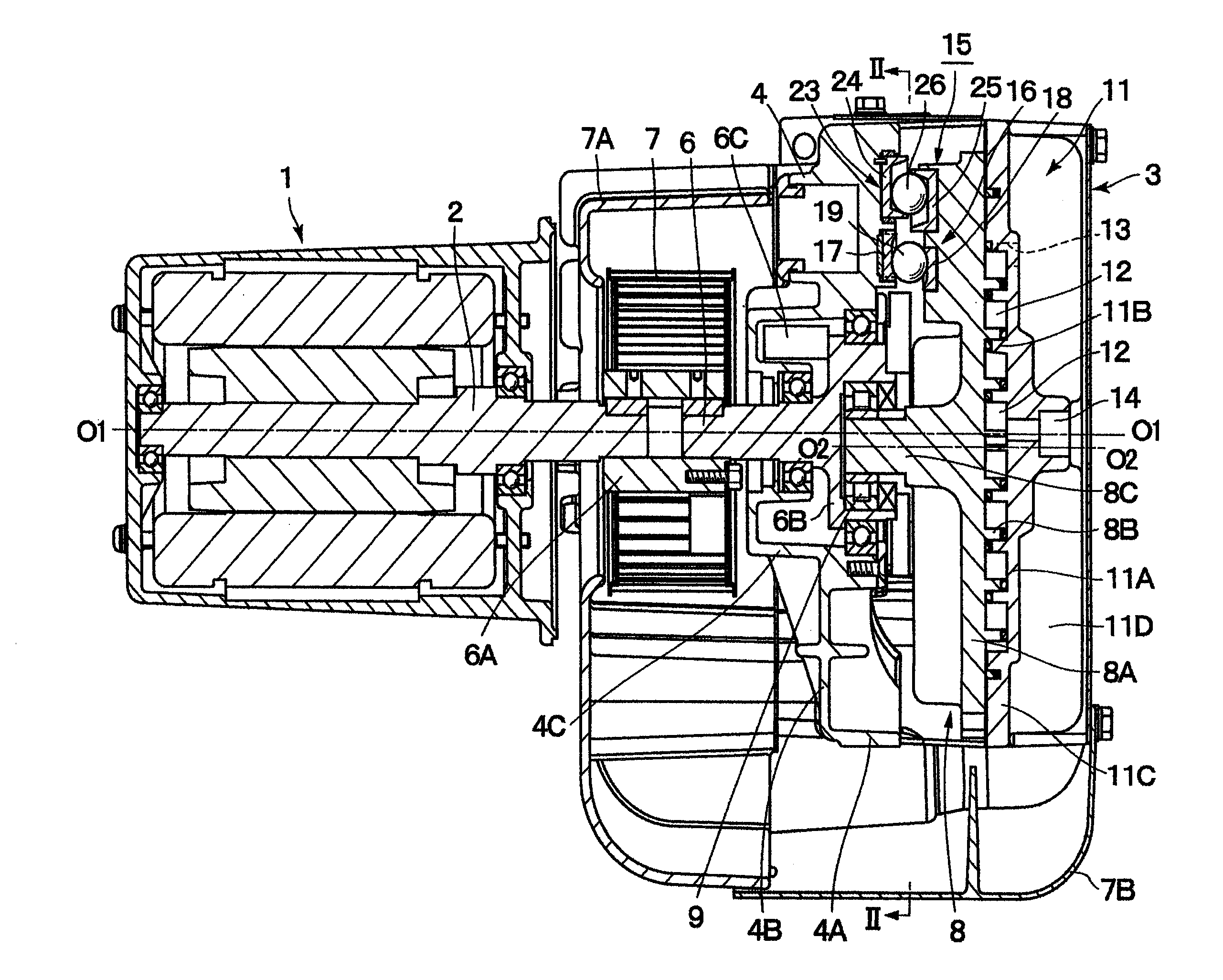
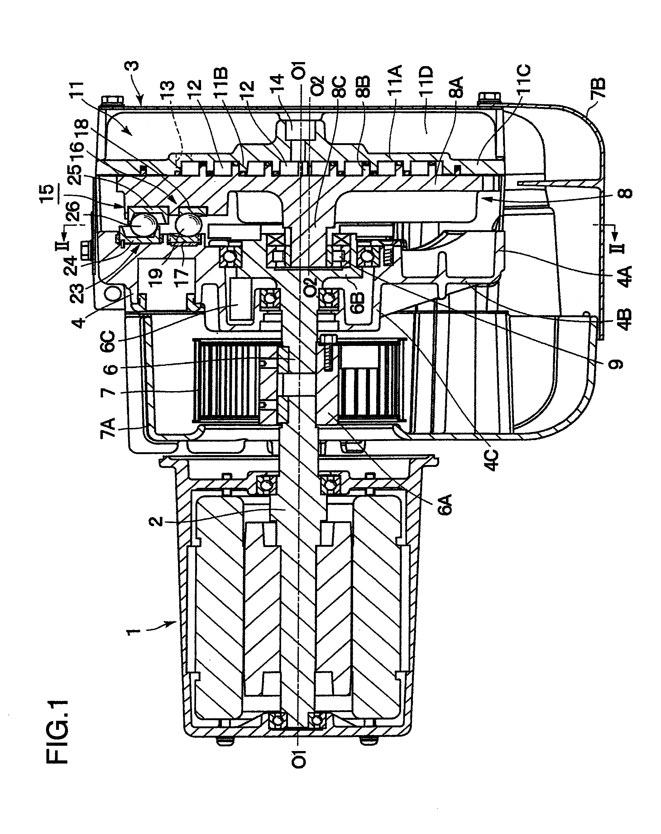
[0028]FIGS. 1 to 6 illustrate a first embodiment according to the present invention. In the drawings, reference numeral 1 denotes an electric motor which constitutes a drive source of an air compressor. The electric motor 1 rotationally drives an output shaft 2 when it receives power supply from the outside, and thereby performs a compression operation of a compressor body 3 (described hereinafter).

[0029]Reference numeral 3 denotes the scroll compressor body which is driven by the electric motor 1. The compressor body 3 includes a casing 4 which constitutes an outer frame of the compressor body 3, a drive shaft 6, an orbiting scroll 8, a fixed scroll 11, and ball coupling devices 15, which will be described hereinafter. The casing 4 of the compressor body 3 and the fixed scroll 11 (described hereinafter) constitute a fixed-side member that is a constituent feature of the present invention.

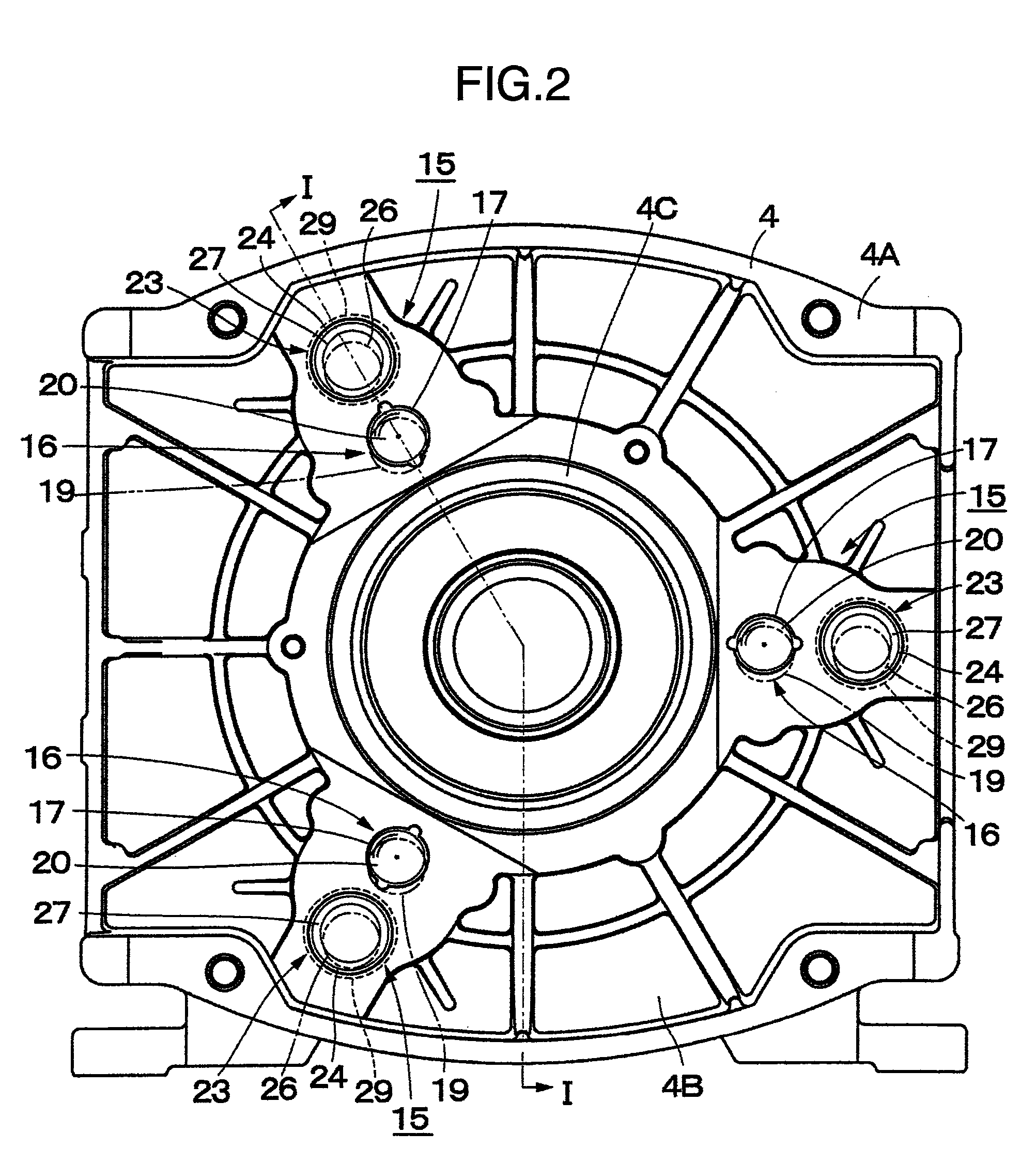
[0030]In this case, the casing 4 is made of metal material such as aluminum, and is formed as a...

fourth embodiment

[0129]FIG. 9 illustrates a fourth embodiment according to the present invention. The fourth embodiment is characterized in that the elastic member is provided on the ball support surfaces of the self-rotation suppressing support members. In the present embodiment, the same components as those in the aforementioned third embodiment are assigned the same reference numerals, and the description thereof is omitted.

third embodiment

[0130]In FIG. 9, reference numeral 61 denotes a ball coupling device employed in the present embodiment. The ball coupling device 61 has the same configuration as that of the ball coupling device 51 described in the third embodiment, and includes the first ball coupling mechanism 16 and a second ball coupling mechanism 62.

[0131]The second ball coupling mechanism 62 includes the self-rotation suppressing support members 24 and 25. The ball support surfaces 24A and 25A of the self-rotation suppressing support members 24 and 25 include the recessed surfaces 27 and 28 composed of the inclined surfaces 27A and 28A and the bottom surfaces 27B and 28B. However, the second ball coupling mechanism 62 is different from that of the third embodiment in that elastic films 64 and 65 (described hereinafter) are provided on the inclined surfaces 27A and 28A of the recessed surfaces 27 and 28.

[0132]Reference numeral 63 denotes a self-rotation preventing ball which constitutes a part of the second ba...


PUM


Abstract

A scroll fluid machine comprises a fixed-side member including a cylindrical casing and a fixed scroll fixed to the casing, and an orbiting scroll and a plurality of ball coupling devices provided between the fixed-side member and the orbiting scroll to prevent self-rotation of the orbiting scroll on its axis and receive a thrust load between the fixed-side member and the orbiting scroll. Each of the ball coupling devices comprises a first ball coupling mechanism for supporting the thrust load generated between the fixed-side member and the orbiting scroll and a second ball coupling mechanism disposed with a space from the first ball coupling mechanism to prevent the self-rotation of the orbiting scroll.

Description

INCORPORATION BY REFERENCE[0001]The present application claims priority from Japanese application JP2008-197995 filed on Jul. 31, 2008, the content of which is hereby incorporated by reference into this application.BACKGROUND OF THE INVENTION[0002]The present invention relates to a scroll fluid machine which is preferably used as an air compressor or a vacuum pump, for example.[0003]As a scroll fluid machine, there is generally known a scroll compressor configured to continuously compress a fluid such as air in compression chambers between an orbiting scroll and a fixed scroll by orbiting the orbiting scroll relative to the fixed scroll without allowing the orbiting scroll to self-rotate on its axis by a drive source such as an electric motor (see JP-A-2006-283673, for example).[0004]In this type of scroll compressor according to the related art, three ball coupling devices are provided between a casing of the compressor and the orbiting scroll, thereby receiving a thrust load (a lo...

Claims


Application Information

Patent Timeline
Patent Type & Authority Applications(United States)
IPC IPC(8): F01C1/02
CPCF04C18/0215F01C17/063
Inventor KOBAYASHI, YOSHIOKANEMOTO, YOSHIYUKIKOMAI, YUJISUEFUJI, KAZUTAKAIWANO, KIMINORI
Owner HITACHI IND EQUIP SYST CO LTD
Why Eureka
Try Eureka