Electrode pack of an electrichemical cell and electrochemical cell with an electrode pack

a technology of electrochemical cells and electrode packs, applied in the direction of wound/folded electrode electrodes, cell components, sustainable manufacturing/processing, etc., can solve the problems of degrading the cell performance, achieve reliable short circuit avoidance, avoid short circuit during folding, and be advantageous for mass production

Inactive Publication Date: 2010-02-04
ROBERT BOSCH GMBH
View PDF5 Cites 0 Cited by
  • Summary
  • Abstract
  • Description
  • Claims
  • Application Information

AI Technical Summary

Benefits of technology

[0005]Preferably, the first support film can be situated on a second separator film. This permits the composite of separator and support films to be folded, thus making it possible to reliably avoid short circuits.
[0006]The separator film can also advantageously be embodied in pocket-like fashion, with at least one of the support films dipping into the pocket-like separator film. It is also possible for both support films to be situated inside a pocket-like separator film. This also makes it possible to reliably avoid short circuits during the folding.
[0007]Preferably, the composite of separator and support films can be folded in zigzag fashion along the longitudinal span. The preferred manufacturing method thus permits a procedure that occurs in an ongoing fashion in lieu of a cyclical one and is therefore advantageous for mass production. This is primarily true when working with very large electrode surfaces of very thin electrodes, i.e. support films. In the manufacture of electrode packs, this applies to the processes of winding or folding as opposed to stacked electrode packs. The continuous production of the electrode packs makes it possible to use them in so-called laminated cells and to assure a stability of the electrode pack. In addition to production related advantages, the improved stability of the electrodes also yields functional advantages for the cells. With the folding, the electrode pack can remain as thin as possible, which is advantageous for heat dissipation from the interior of the cell and therefore for its long-term stability.
[0012]The output conductors can protrude transversely in relation to the longitudinal span of the support films. The output conductors can be attached by means of soldering or welding to the parts of the support films protruding from the separator films. The dimensioning of the output conductors is appropriately matched to an expected decrease in performance. It is thus possible to improve a leak tightness of the cell. The protruding regions of the support films that are not attached to the output conductors can be advantageously covered with an insulation. It is thus possible to use a non-laminated metal foil as the outer skin of the cell.
[0014]If the electrode pack is provided with a stabilization that stabilizes the distance between the support films in the folded state, it is then possible to maintain a constant distance between electrodes and a high functional stability of the cell over the service life of the cell, even in the presence of powerful stress. The stabilization can be provided by wrapping or by attaching plastic clamps or the like. It is thus possible to maintain the original distance of the support films from one another, i.e. the distance between the electrodes in the electrode pack, and to prevent the active substance on the support film from drying out. Otherwise, cavities could form that the existing electrolyte would be insufficient to fill, thus causing the active substance on the support film to dry out.

Problems solved by technology

The strain induced by charging and discharging cycles and temperature cycles can lead to a change in this distance, which degrades the performance of the cell.

Method used


Image

  • Electrode pack of an electrichemical cell and electrochemical cell with an electrode pack
  • Electrode pack of an electrichemical cell and electrochemical cell with an electrode pack
  • Electrode pack of an electrichemical cell and electrochemical cell with an electrode pack

Examples


Embodiment Construction

[0022]Components that are the same or similar have been provided with the same reference numerals in the drawings.

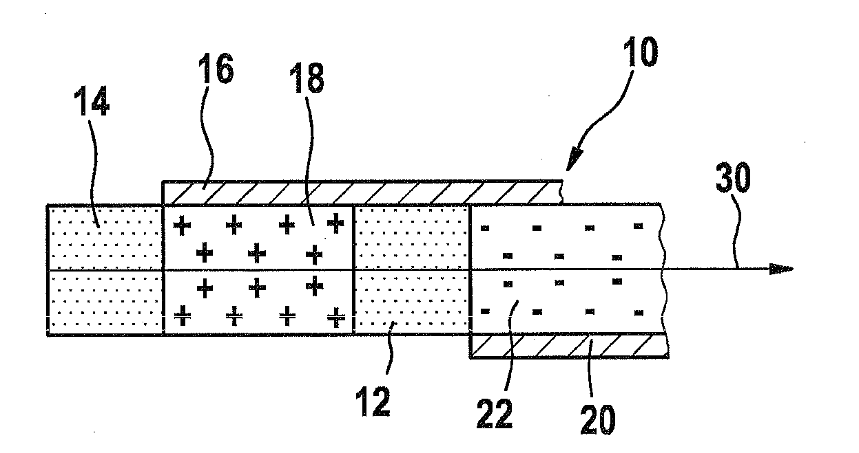
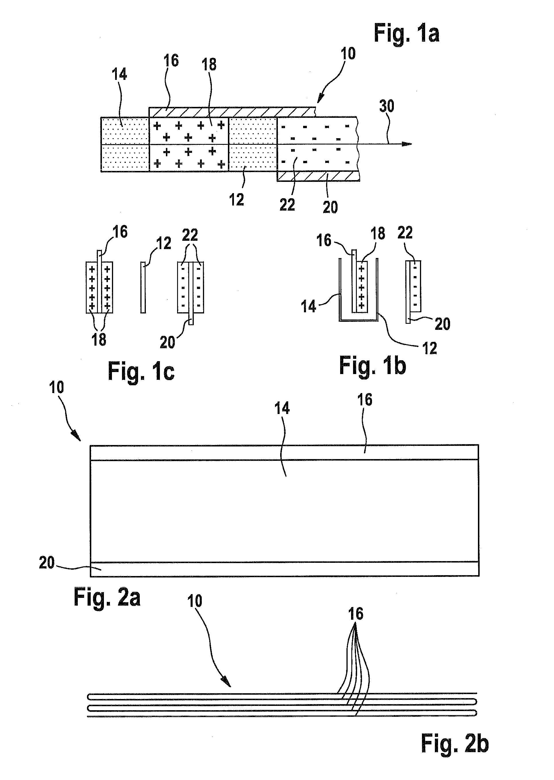
[0023]FIG. 1a is an exploded top view of a composite of support films 16, 20 and separator films 12, 14 of a preferred electrode pack 10 belonging to an electrochemical cell that is not shown. FIG. 1b is a top view of one end of an alternative embodiment with a pocket-like separator film 14, with the support films 16 and 20 being coated with an electrochemically active substance 18, 22 on one side. FIG. 1c shows an embodiment in which the support films 16 and 20 are each coated with an electrochemically active substance 18, 22 on both sides (spacing distances not shown to scale).

[0024]The first support film 16 is coated with the electrochemically active substance 18 and the second support film 20 is coated with the electrochemically active substance 22. A separator film 12 is positioned between the two support films 16, 20. The first support film 16 rests on a separator ...


PUM

PropertyMeasurementUnit
lengthaaaaaaaaaa
heightaaaaaaaaaa
distanceaaaaaaaaaa

Abstract

The invention relates to an electrode pack of an electrochemical cell (40), which has en essentially flat design and comprises laterally protruding connecting lugs (24, 26) for making electrical contact. According to the invention, a first carrier film (16) coated with an electrochemical active mass (18) and a second carrier film (20) coated with an electrochemical active mass (22) are separated by a first separator film (12), characterized in that the first carrier film (16) protrudes on the longitudinal side along the longitudinal extension (30) of the separator film (12) while the second carrier film (20) protrudes on the opposite longitudinal side of the separator film (12).

Description

PRIOR ART[0001]The invention is based on an electrode pack of an electrochemical cell and an electrochemical cell with an electrode pack as recited in the preambles to the independent claims.[0002]In sophisticated traction systems such as hybrid vehicles, powerful electrical storage cells are required. There are a wide variety of known lithium-ion cells used for this purpose. They are frequently round or prismatic, with stacked, wound, or folded electrode packs. As a reasonably priced and powerful system, there are known lithium-ion batteries of the kind described in EP 1 577 973 A1, which describes so-called “coffee bag” cells embodied in the form of rectangular, flat cells. In cells of this kind, the electrode packs are contained in a laminated metal foil that is adapted to the electrode pack. The cells are correspondingly soft. They are usually assembled into a plurality of modules and electrically connected in parallel and / or in series. For the function of the cell, it is necess...

Claims


Application Information

Patent Timeline
Patent Type & Authority Applications(United States)
IPC IPC(8): H01M2/16H01M50/119H01M50/466H01M50/531H01M50/572
CPCH01M2/0267H01M2/0275H01M2/0285H01M2/18H01M2/26H01M2/34Y02T10/7011H01M10/0413H01M10/0418H01M10/0431H01M10/0525Y02E60/122H01M4/70Y02E60/10H01M50/531H01M50/572Y02P70/50H01M50/466H01M50/119H01M50/543Y02T10/70
Inventor AUMAYER, RICHARD
Owner ROBERT BOSCH GMBH
Why Eureka
Try Eureka