Turbomachine injection nozzle including a coolant delivery system

a technology of injection nozzle and coolant, which is applied in the direction of machines/engines, combustion types, lighting and heating apparatus, etc., can solve the problems of nox, flame holding, and nitrogen oxide levels, and achieve the effect of reducing operating efficiency

Active Publication Date: 2010-02-11
GENERAL ELECTRIC CO
View PDF38 Cites 101 Cited by
  • Summary
  • Abstract
  • Description
  • Claims
  • Application Information

AI Technical Summary

Problems solved by technology

Unfortunately, higher gas stream temperatures produce higher levels of nitrogen oxide (NOx), an emission that is subject to both federal and state regulation.
The high flame speed often results in flame holding that detracts from operating efficiency and has a negative impact on operational life of turbine components.

Method used


Image

  • Turbomachine injection nozzle including a coolant delivery system
  • Turbomachine injection nozzle including a coolant delivery system
  • Turbomachine injection nozzle including a coolant delivery system

Examples


Embodiment Construction

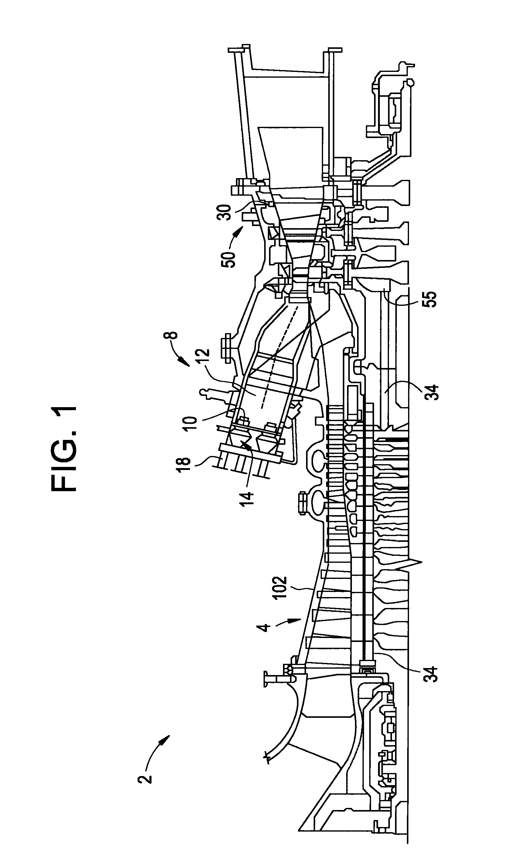
[0011]FIG. 1 is a schematic illustration of an exemplary gas turbine engine 2. Engine 2 includes a compressor 4 and a combustor assembly 8. Combustor assembly 8 includes a combustor assembly wall 10 that at least partially defines a combustion chamber 12. A pre-mixing apparatus or injection nozzle 14 extends through combustor assembly wall 10 and leads into combustion chamber 12. As will be discussed more fully below, injection nozzle 14 receives a first fluid or fuel through a fuel inlet 18 and a second fluid or compressed air from compressor 4. The fuel and compressed air are mixed, passed into combustion chamber 12 and ignited to form a high temperature, high pressure combustion product or air stream. Although only a single combustor assembly 8 is shown in the exemplary embodiment, engine 2 may include a plurality of combustor assemblies 8 arranged in, for example, a can annular array. In any event, engine 2 also includes a turbine 30 operatively connected to a compressor / turbine...


PUM


Abstract

An injection nozzle for a turbomachine includes a main body having a first end portion that extends to a second end portion defining an exterior wall having an outer surface. A plurality of fluid delivery tubes extend through the main body. Each of the plurality of fluid delivery tubes includes a first fluid inlet for receiving a first fluid, a second fluid inlet for receiving a second fluid and an outlet. The injection nozzle further includes a coolant delivery system arranged within the main body. The coolant delivery system guides a coolant along at least one of a portion of the exterior wall and around the plurality of fluid delivery tubes.

Description

[0001]This invention was made with Government support under Contract No. DE-FC26-05NT4263, awarded by the US Department of Energy (DOE). The Government has certain rights in this invention.BACKGROUND OF THE INVENTION[0002]Exemplary embodiments of the present invention relate to the art of turbomachine injection nozzles and, more particularly, to turbomachine injection nozzles including a coolant delivery system.[0003]In general, gas turbine engines combust a fuel / air mixture which releases heat energy to form a high temperature gas stream. The high temperature gas stream is channeled to a turbine via a hot gas path. The turbine converts thermal energy from the high temperature gas stream to mechanical energy that rotates a turbine shaft. The turbine may be used in a variety of applications, such as for providing power to a pump or an electrical generator.[0004]In a gas turbine, engine efficiency increases as combustion gas stream temperatures increase. Unfortunately, higher gas stre...

Claims


Application Information

Patent Timeline
Patent Type & Authority Applications(United States)
IPC IPC(8): F02C7/12B05B15/00B05B7/04
CPCF23D14/78F23D2214/00F23R2900/00002F23R3/286F23R3/283
Inventor ZUO, BAIFANG
Owner GENERAL ELECTRIC CO
Why Eureka
Try Eureka