Suspension system for vehicle

a suspension system and vehicle technology, applied in the direction of mechanical equipment, vibration suppression adjustment, transportation and packaging, etc., can solve the problems of limiting the amount of actuator force that can be generated by the actuator, deteriorating riding comfort, and insufficient actuator force, so as to achieve the effect of appropriate body postur

Inactive Publication Date: 2010-02-11
TOYOTA JIDOSHA KK
View PDF0 Cites 12 Cited by
  • Summary
  • Abstract
  • Description
  • Claims
  • Application Information

AI Technical Summary

Benefits of technology

[0074]The above form (24) may employ an arrangement in which the limit values of the left and right wheels are made the same, an arrangement in which a ratio of the limit value of the front wheel to the limit value of the rear wheel is set at a specific value, and an arrangement in which those two arrangements are integrated. Where the third arrangement is employed, the roll rigidity distribution can be easily maintained. According to the form, even when the posture control component in the actuator that corresponds to any one of the four wheels is limited, the posture control components of the actuators that respectively correspond to the other three wheels are automatically controlled, making it possible to maintain an appropriate body posture.

Problems solved by technology

There exists, however, a limit in an amount of an actuator force that can be generated by the actuator, due to restrictions on and limitations to an electrifying current amount of an electric motor of the actuator and a supply current amount from an electric power source to the electric motor.
Accordingly, where the vibration damping control and the body-posture control are simultaneously executed, there may arise a situation in which the actuator force becomes insufficient.
The insufficiency in the actuator force leads to a deterioration in the riding comfort as felt by vehicle passengers and a deterioration in the steerability and the stability of the vehicle.
The electromagnetic suspension system is still under development and suffers from various problems in addition to the above-indicated problem of the insufficiency of the actuator force.

Method used


Image

  • Suspension system for vehicle
  • Suspension system for vehicle
  • Suspension system for vehicle

Examples


first embodiment

i) Structure of Suspension System

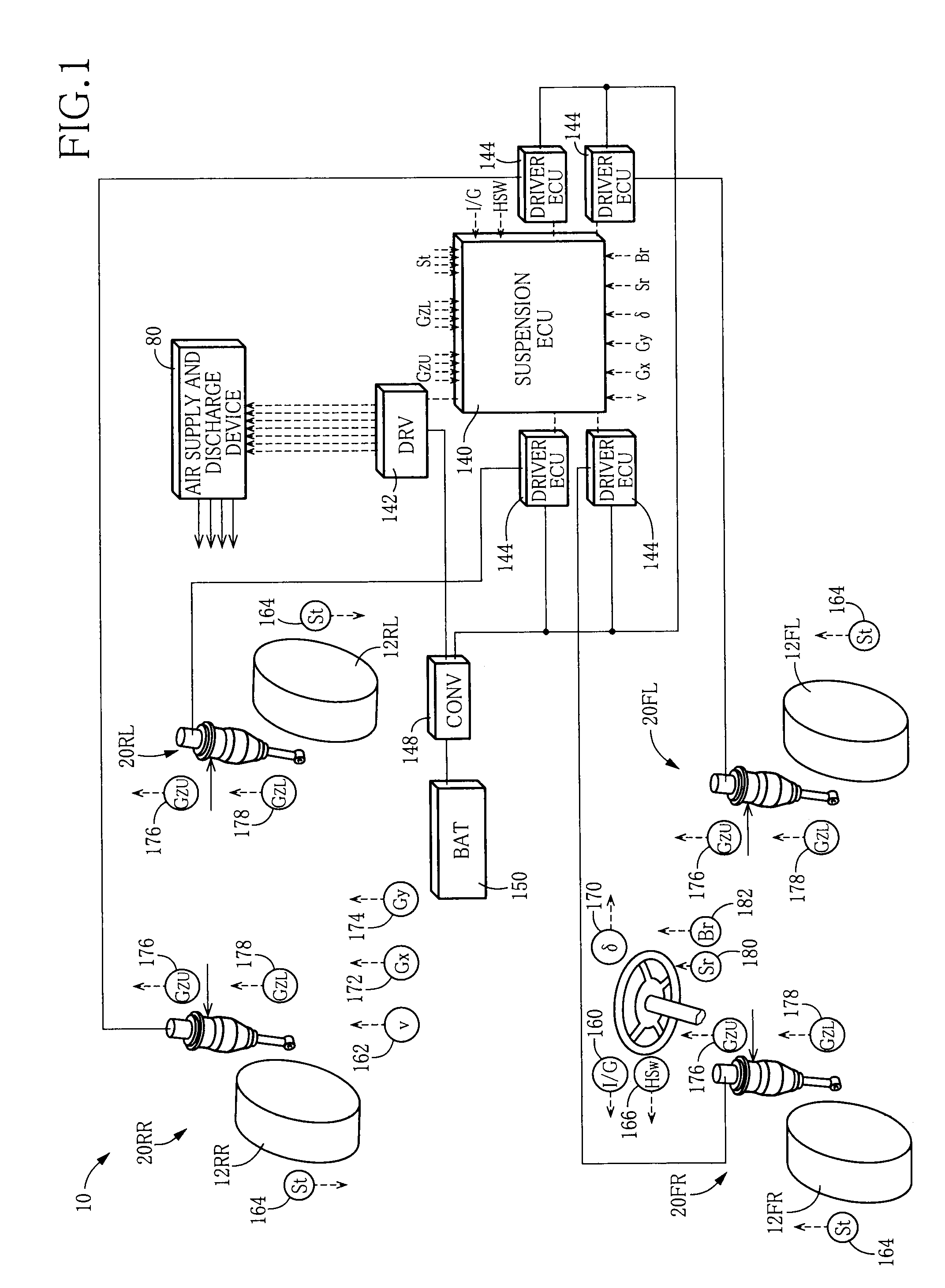
[0089]FIG. 1 schematically shows a suspension system 10 for a vehicle according to a first embodiment. The suspension system 10 includes four independent suspension apparatus which respectively correspond to four wheels 12, namely, a front left wheel, a front right wheel, a rear left wheel, and a rear right wheel. Each of the suspension apparatus includes a spring•absorber Assy 20 in which a suspension spring and a shock absorber are united. The four wheels 12 and the four spring•absorber Assys 20 are collectively referred to as the wheel 12 and the spring•absorber Assy 20, respectively. Where it is necessary to distinguish the four wheels 12 from each other and to distinguish the four spring•absorber Assys 20 from each other, there are attached suffixes “FL”, “FR”, “RL”, and “RR” respectively indicating the front left wheel, the front right wheel, the rear left wheel, and the rear right wheel.

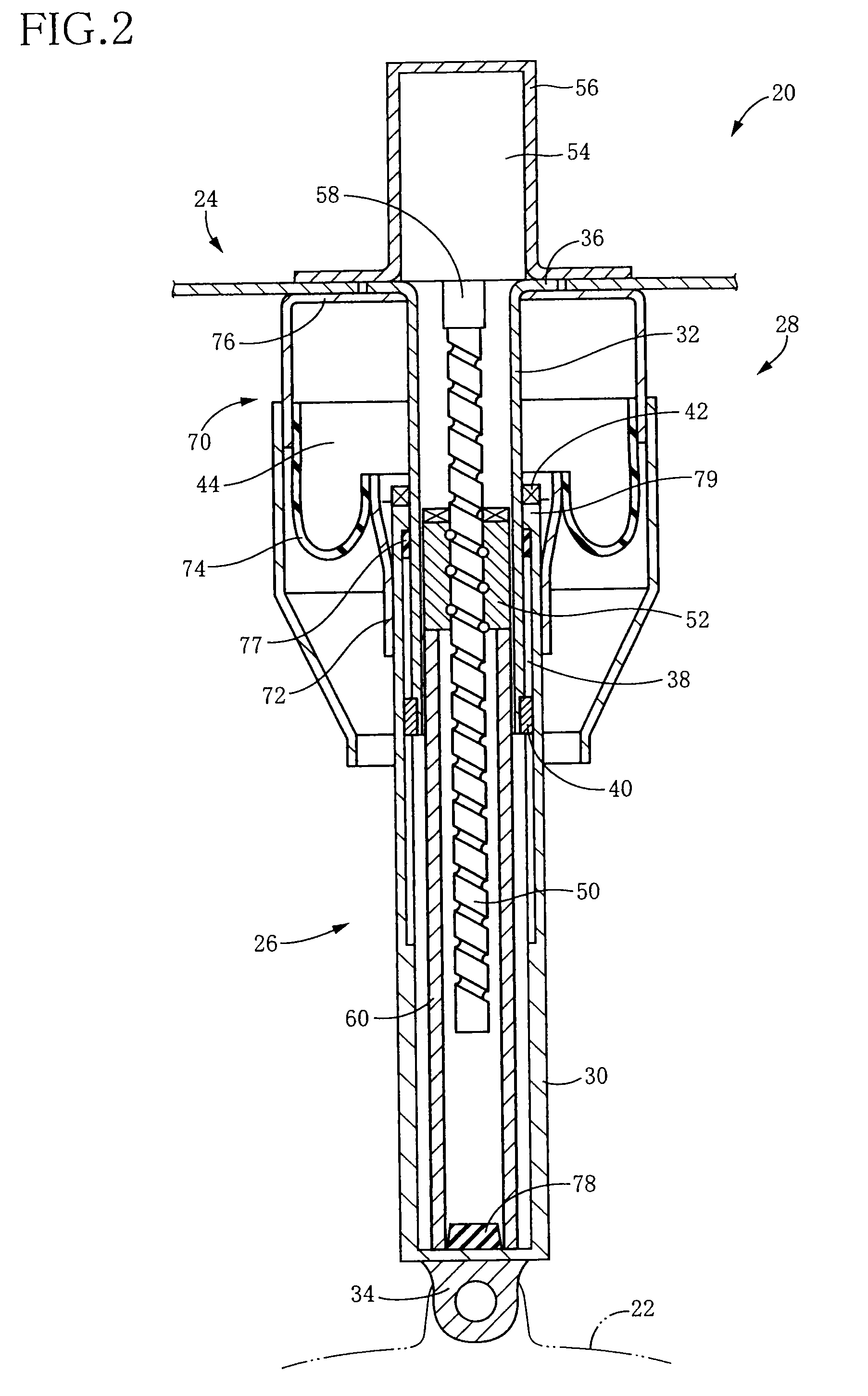
[0090]As shown in FIG. 2, the spring•absorber Assy 20 inc...

second embodiment

[0116]A suspension system for a vehicle according to a second embodiment is identical in hardware structure with the system in the illustrated first embodiment. In the following explanation, therefore, the same reference numerals as used in the first embodiment are used to identify the corresponding components having the same function as in the first embodiment, and a detailed explanation of which is dispensed with. The system of the second embodiment differs from the system of the first embodiment in the control by the suspension ECU. Accordingly, the control by the suspension ECU according to the present embodiment will be hereinafter explained.

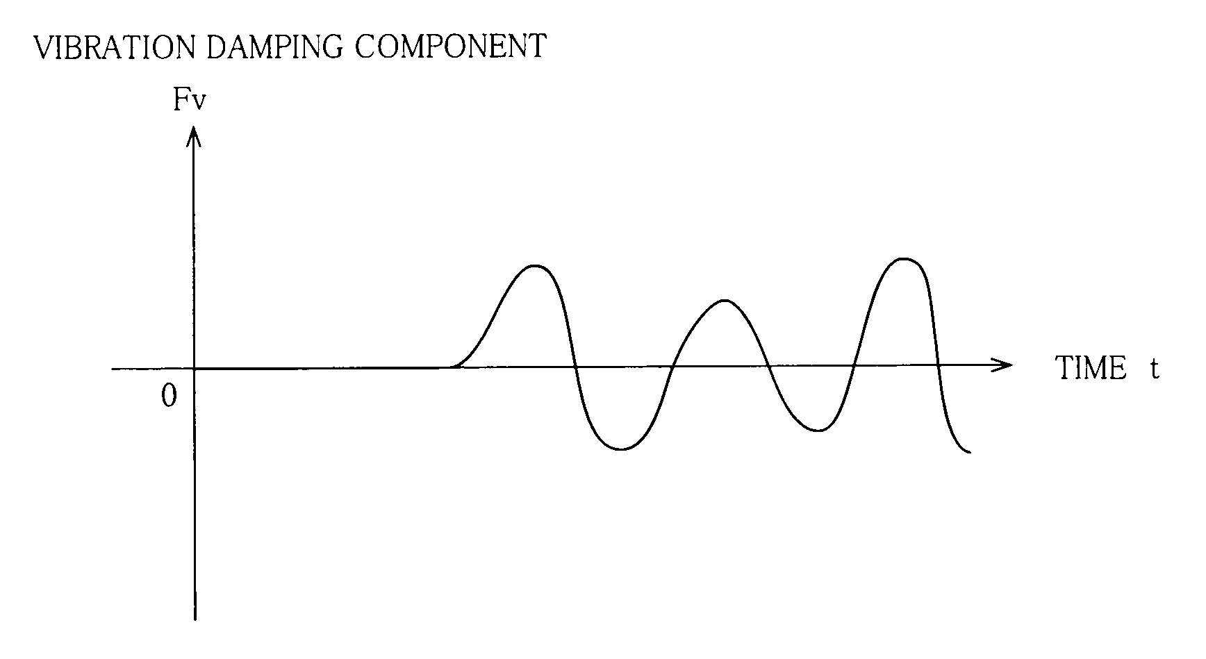
[0117]In the suspension system according to the second embodiment, the posture-control-component limiting control in the suspension ECU 140 is arranged to change the posture-control-component limit value based on an intensity of a vibration of the sprung portion (i.e., a sprung vibration). The intensity of the sprung vibration is judged bas...

third embodiment

[0120]A suspension system for a vehicle according to a third embodiment is also identical in hardware structure with the system in the illustrated first embodiment. In the following explanation, therefore, the same reference numerals as used in the first embodiment are used to identify the corresponding components having the same function as in the first embodiment, and a detailed explanation of which is dispensed with. The system of the third embodiment differs from the system of the first embodiment in the control by the suspension ECU. Accordingly, the control by the suspension ECU according to the present embodiment will be hereinafter explained.

[0121]While the actuator force is utilized in the control of the actuator 26 in the suspension system in the first embodiment, the electrifying current amount which is a related amount of the actuator force indicative of the magnitude of the actuator force is utilized in the third embodiment. Accordingly, the vibration damping control an...


PUM


Abstract

In a system in which an actuator force to be generated by an actuator is controlled based on a component sum that is a sum of a vibration damping component as the actuator force to be generated in a vibration damping control and a posture control component that is the actuator force to be generated in a body-posture control, a control in which the posture control component is limited so as to be not larger than a limit value is executable. The system ensures the actuator force that should be generated in the vibration damping control by limiting the posture control component, in a situation in which there is a limit in the actuator force that can be generated. Accordingly, a sufficient amount of a damping force can be generated, so that riding comfort of the vehicle and the like is prevented from being deteriorated.

Description

TECHNICAL FIELD[0001]The present invention relates to a suspension system including an electromagnetic actuator configured to apply, to a sprung portion and an unsprung portion, a force in a direction in which the sprung portion and the unsprung portion are moved toward and away from each other.BACKGROUND ART[0002]In recent years, there has been developed, as a suspension system for a vehicle, the so-called electromagnetic suspension system including an electromagnetic actuator configured to apply, to a sprung portion and an unsprung portion, a force in a direction in which the sprung portion and the unsprung portion are moved toward and away from each other. For instance, the following Patent Documents disclose such an electromagnetic suspension system. Each of the disclosed suspension systems is expected as a high-performance suspension system in view of an advantage that it is possible to easily realize a suspension characteristic based on the so-called skyhook theory.[0003]Paten...

Claims


Application Information

Patent Timeline
Patent Type & Authority Applications(United States)
IPC IPC(8): B60G17/016
CPCB60G11/27B60G15/067B60G17/0157F16F2232/04B60G2202/42F16F15/002B60G2202/152
Inventor INOUE, HIROFUMI
Owner TOYOTA JIDOSHA KK
Why Eureka
Try Eureka