Suspension system for vehicle
a suspension system and vehicle technology, applied in the direction of mechanical equipment, vibration suppression adjustment, transportation and packaging, etc., can solve the problems of limiting the amount of actuator force that can be generated by the actuator, deteriorating riding comfort, and insufficient actuator force, so as to achieve the effect of appropriate body postur
- Summary
- Abstract
- Description
- Claims
- Application Information
AI Technical Summary
Benefits of technology
Problems solved by technology
Method used
Image
Examples
first embodiment
i) Structure of Suspension System
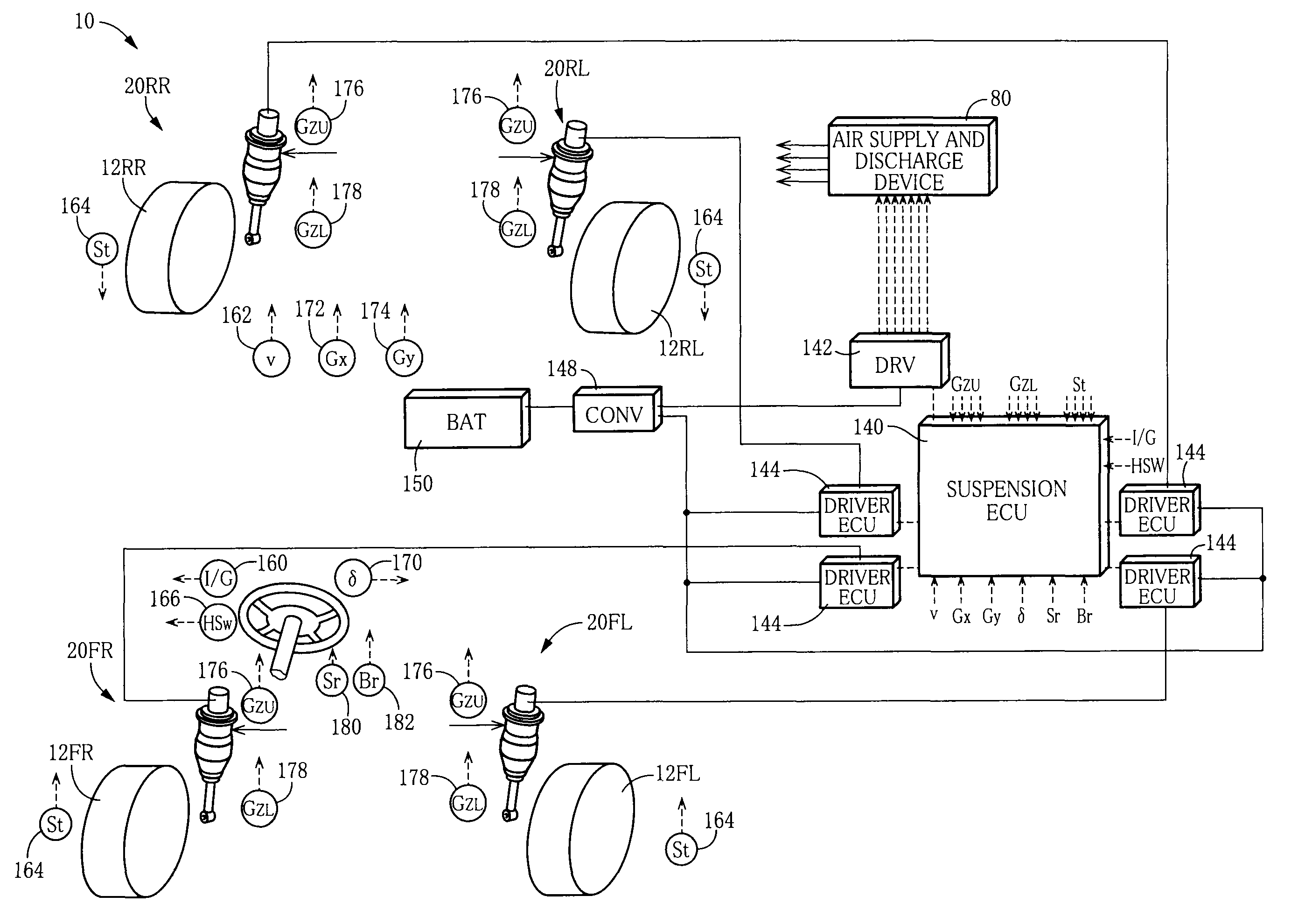
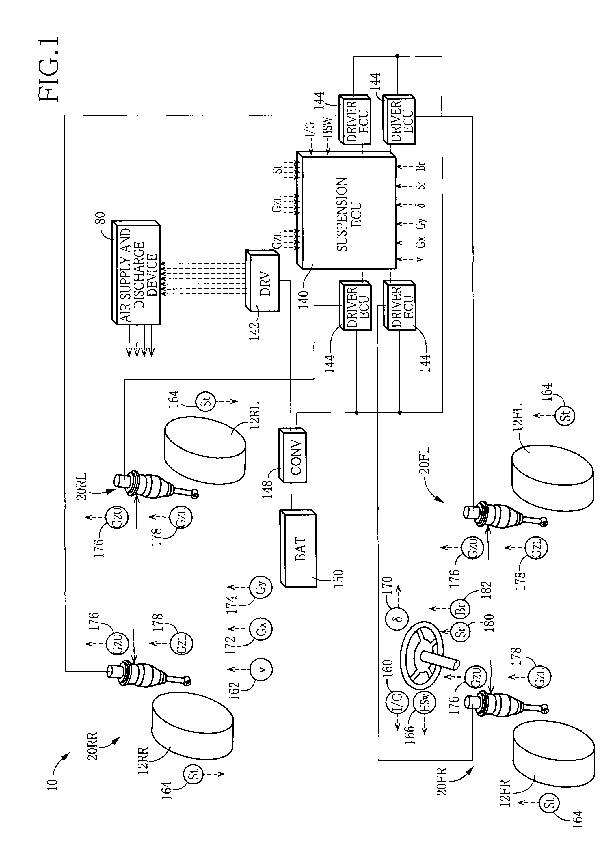
[0089]FIG. 1 schematically shows a suspension system 10 for a vehicle according to a first embodiment. The suspension system 10 includes four independent suspension apparatus which respectively correspond to four wheels 12, namely, a front left wheel, a front right wheel, a rear left wheel, and a rear right wheel. Each of the suspension apparatus includes a spring•absorber Assy 20 in which a suspension spring and a shock absorber are united. The four wheels 12 and the four spring•absorber Assys 20 are collectively referred to as the wheel 12 and the spring•absorber Assy 20, respectively. Where it is necessary to distinguish the four wheels 12 from each other and to distinguish the four spring•absorber Assys 20 from each other, there are attached suffixes “FL”, “FR”, “RL”, and “RR” respectively indicating the front left wheel, the front right wheel, the rear left wheel, and the rear right wheel.
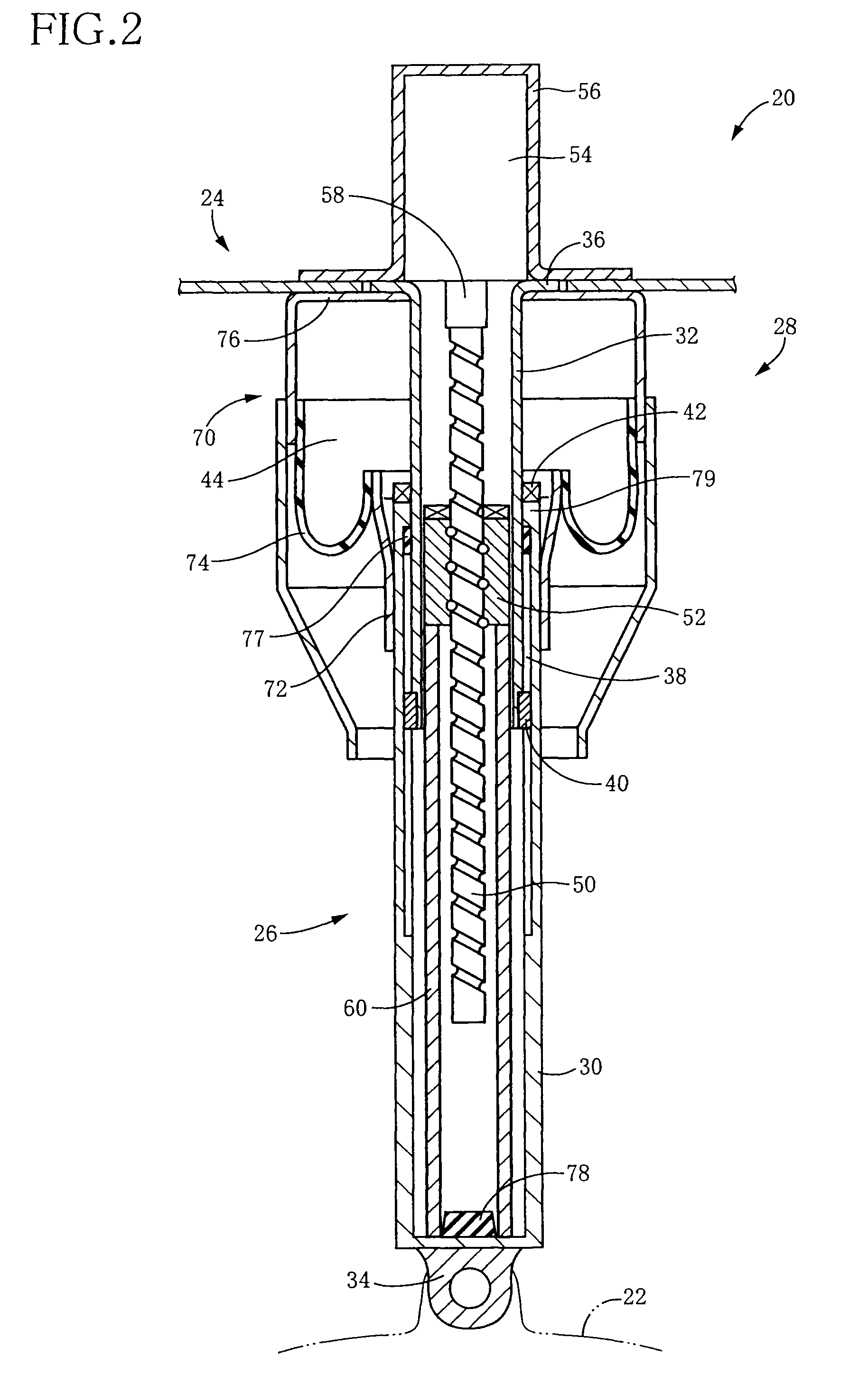
[0090]As shown in FIG. 2, the spring•absorber Assy 20 inc...
second embodiment
[0116]A suspension system for a vehicle according to a second embodiment is identical in hardware structure with the system in the illustrated first embodiment. In the following explanation, therefore, the same reference numerals as used in the first embodiment are used to identify the corresponding components having the same function as in the first embodiment, and a detailed explanation of which is dispensed with. The system of the second embodiment differs from the system of the first embodiment in the control by the suspension ECU. Accordingly, the control by the suspension ECU according to the present embodiment will be hereinafter explained.
[0117]In the suspension system according to the second embodiment, the posture-control-component limiting control in the suspension ECU 140 is arranged to change the posture-control-component limit value based on an intensity of a vibration of the sprung portion (i.e., a sprung vibration). The intensity of the sprung vibration is judged bas...
third embodiment
[0120]A suspension system for a vehicle according to a third embodiment is also identical in hardware structure with the system in the illustrated first embodiment. In the following explanation, therefore, the same reference numerals as used in the first embodiment are used to identify the corresponding components having the same function as in the first embodiment, and a detailed explanation of which is dispensed with. The system of the third embodiment differs from the system of the first embodiment in the control by the suspension ECU. Accordingly, the control by the suspension ECU according to the present embodiment will be hereinafter explained.
[0121]While the actuator force is utilized in the control of the actuator 26 in the suspension system in the first embodiment, the electrifying current amount which is a related amount of the actuator force indicative of the magnitude of the actuator force is utilized in the third embodiment. Accordingly, the vibration damping control an...
PUM
 Abstract
Description
Claims
Application Information
 - R&D
- Intellectual Property
- Life Sciences
- Materials
- Tech Scout
- Unparalleled Data Quality
- Higher Quality Content
- 60% Fewer Hallucinations
Browse by: Latest US Patents, China's latest patents, Technical Efficacy Thesaurus, Application Domain, Technology Topic, Popular Technical Reports.
© 2025 PatSnap. All rights reserved.Legal|Privacy policy|Modern Slavery Act Transparency Statement|Sitemap|About US| Contact US: help@patsnap.com


