Signal processing device, radar device, vehicle control device, and signal processing method

a technology of radar device and signal processing method, which is applied in the direction of measurement device, using reradiation, instruments, etc., can solve the problems of limiting the relative distance and relative velocities which can be detected, and the detection of beat frequency is no longer possible, so as to prevent the delay in the output of detection results from the radar device to the vehicle control device.

Active Publication Date: 2010-02-11
FUJITSU GENERAL LTD
View PDF13 Cites 22 Cited by
  • Summary
  • Abstract
  • Description
  • Claims
  • Application Information

AI Technical Summary

Benefits of technology

The patent describes a radar device that can detect the distance and velocity of objects using a combination of beat signals generated in different transmission intervals. This allows for different detection processes to be performed in a single detection cycle, and ensures that the same relative distance and velocity can be detected in a small number of detection cycles. This prevents delay in output of detection results to a vehicle control device.

Problems solved by technology

The technical problem addressed in this patent text relates to improving the detection capabilities of radar devices for vehicles by quickly approaching target objects at short distances without causing delays in controlling the vehicle. A solution involves utilizing different methods for frequency modulation during transmission and combination of beat signals to determine the relative distance and velocity of the targets. However, current techniques require multiple detection cycles and may experience issues with synchronization and latency.

Method used


Image

  • Signal processing device, radar device, vehicle control device, and signal processing method
  • Signal processing device, radar device, vehicle control device, and signal processing method
  • Signal processing device, radar device, vehicle control device, and signal processing method

Examples


Embodiment Construction

[0034]Below, an aspect of the invention is explained referring to the drawings. However, the technical scope of the invention is not limited to this aspect, but extends to the inventions described in the Scope of Claims, and to inventions equivalent thereto.

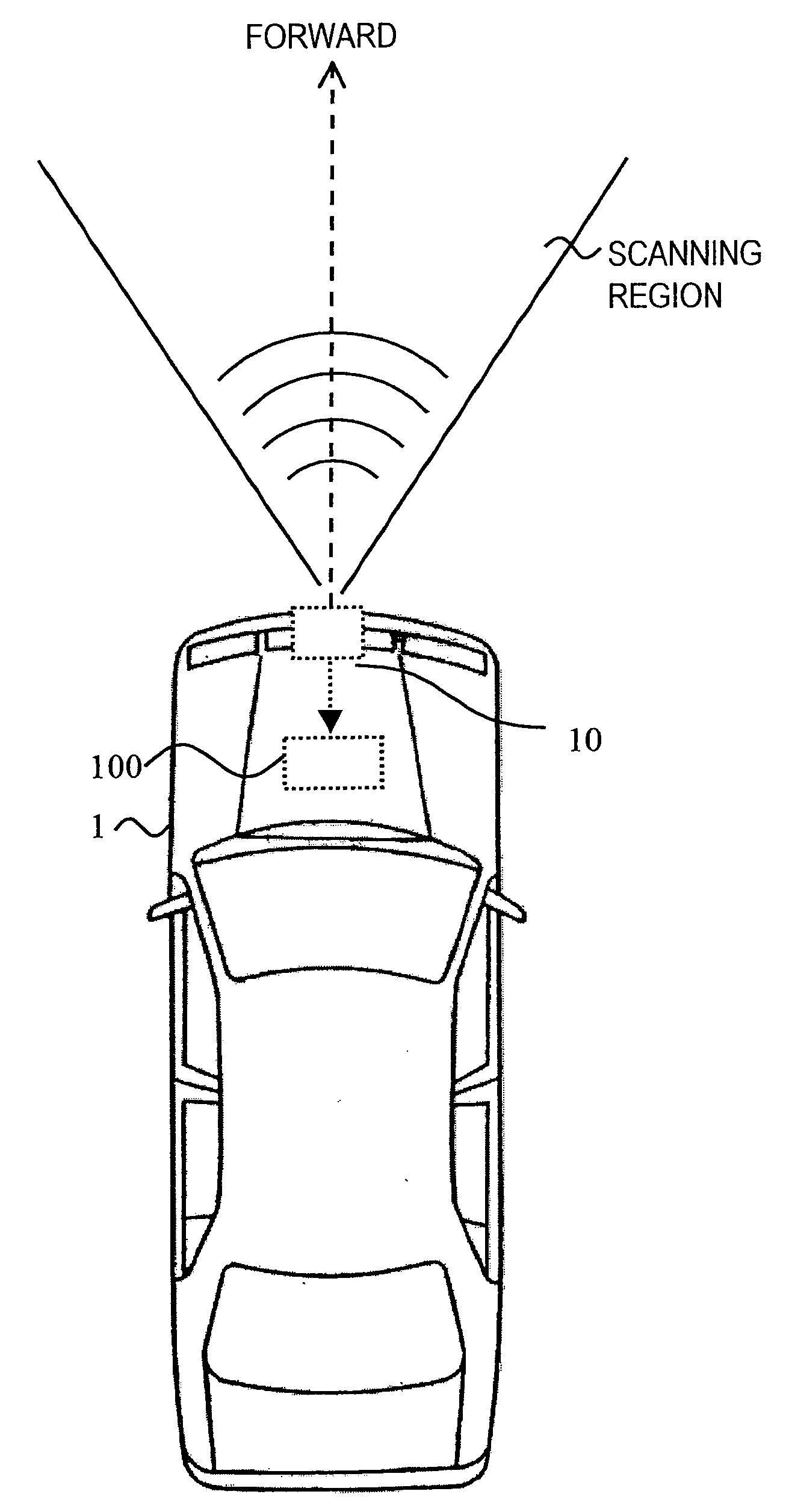
[0035]FIG. 4 explains the circumstances of use of a radar device to which this invention is applied. As one example, an FM-CW radar device 10 is installed in the front grill or within the bumper in the front portion of a vehicle 1, and transmits millimeter-wave radar signals (electromagnetic waves) in a scanned region in the forward direction of the vehicle 1, passing through a radome formed in the front face of the front grill or bumper, as well as receiving signals reflected from the scanned region.

[0036]The radar device 10 generates beat signals from the transmitted and received signals, and by processing these beat signals using a microcomputer or other signal processing device, the relative distance and relative velocity of ...


PUM


Abstract

In order to prevent delays in output of detection results, even when a plurality of frequency modulation methods with different frequency change rates are used, an FM-CW radar device employing frequency modulation with two different frequency change rates, has distance/velocity detection unit for detecting the relative distance or relative velocity of a target object based on beat signals of transmission signals with the same frequency change rate and for detecting the relative distance or relative velocity using beat signals when the frequency change rates are different, and distance/velocity confirmation unit for adding evaluation values for relative distances or relative velocities detected in the detection processing, and for confirming the relative distance or relative velocity based on the evaluation value which has reached a criterion value. As a result, more data can be obtained in one detection cycle, and the same advantageous results as when executing a plurality of detection cycles can be obtained. Consequently, delay of output of detection results from the radar device to a vehicle control device can be prevented.

Description


Claims


Application Information

Patent Timeline
Owner FUJITSU GENERAL LTD
Why Eureka
Try Eureka