Globe deployable LED light assembly

Inactive Publication Date: 2010-02-11
RELUME TECH
View PDF9 Cites 19 Cited by
  • Summary
  • Abstract
  • Description
  • Claims
  • Application Information

AI Technical Summary

Benefits of technology

[0011]The subject invention provides an L.E.D. light assembly properly designed for effective thermal management, capable of being inserted through the narrow opening of a globe, and capable of being canted at range of desired angles toward the ground. The elongated sections of the heat sink are spaced from one another to effectively transfer heat transfer away from the L.E.D.s., which prevents early degradation of the L.E.D.s. The deployment mechanism provides a simple and cost effective way for the elon

Problems solved by technology

However, existing properly designed L.E.D. light assemblies, such as the light assembly disclosed in the Hochstein patent application, do not fit through the narrow opening of the globe.
L.E.D. light assemblies currently used in globes do not provide effective thermal management.
In

Method used


Image

  • Globe deployable LED light assembly
  • Globe deployable LED light assembly
  • Globe deployable LED light assembly

Examples


Example

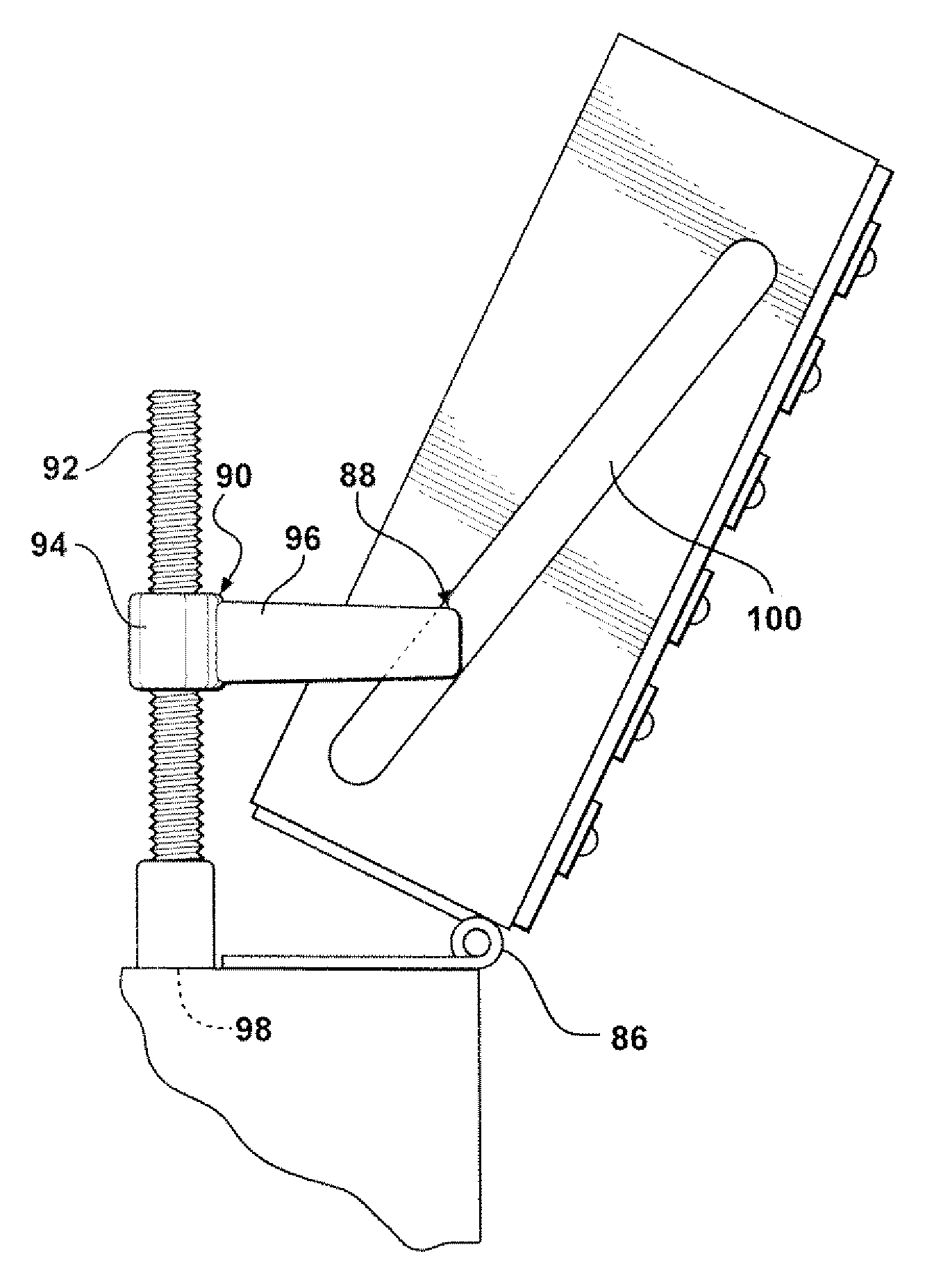
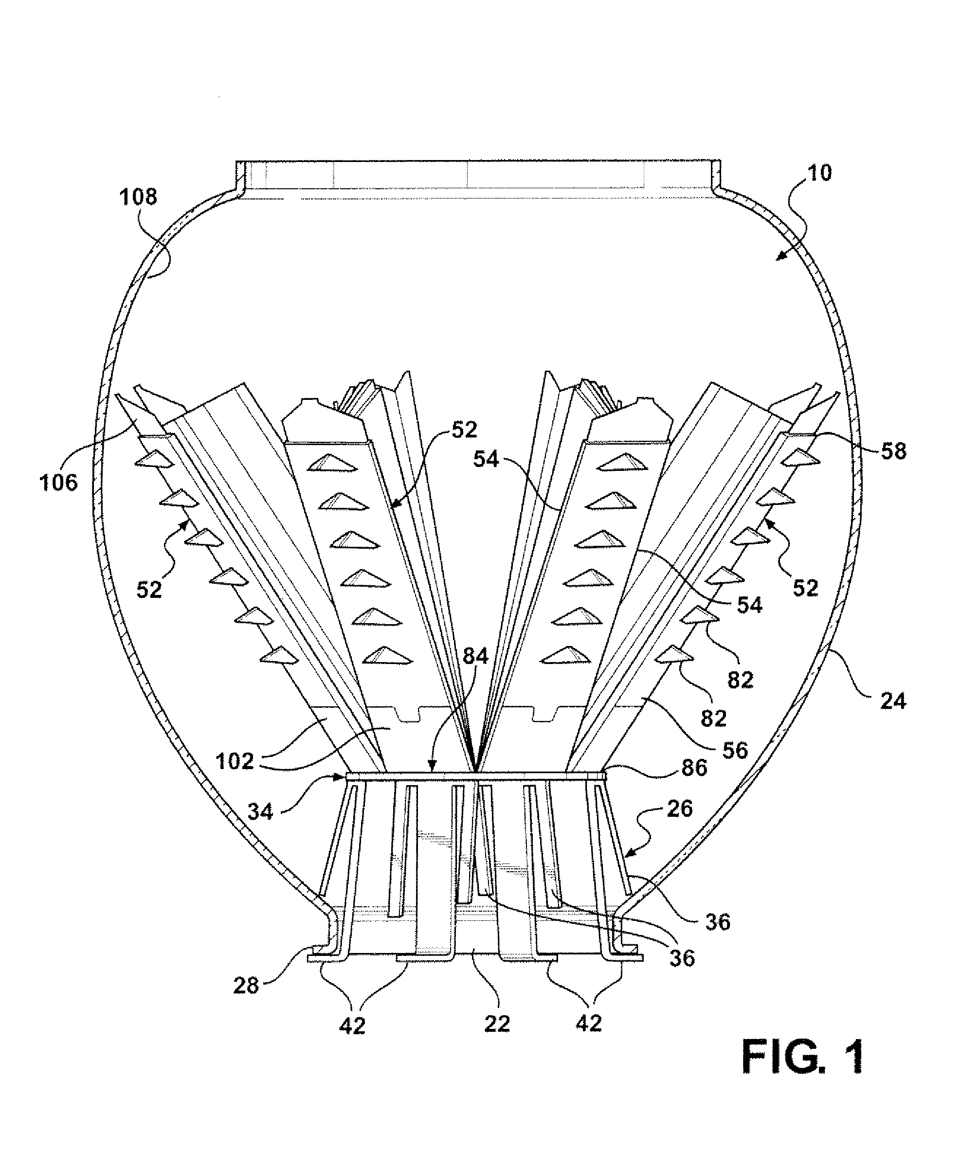
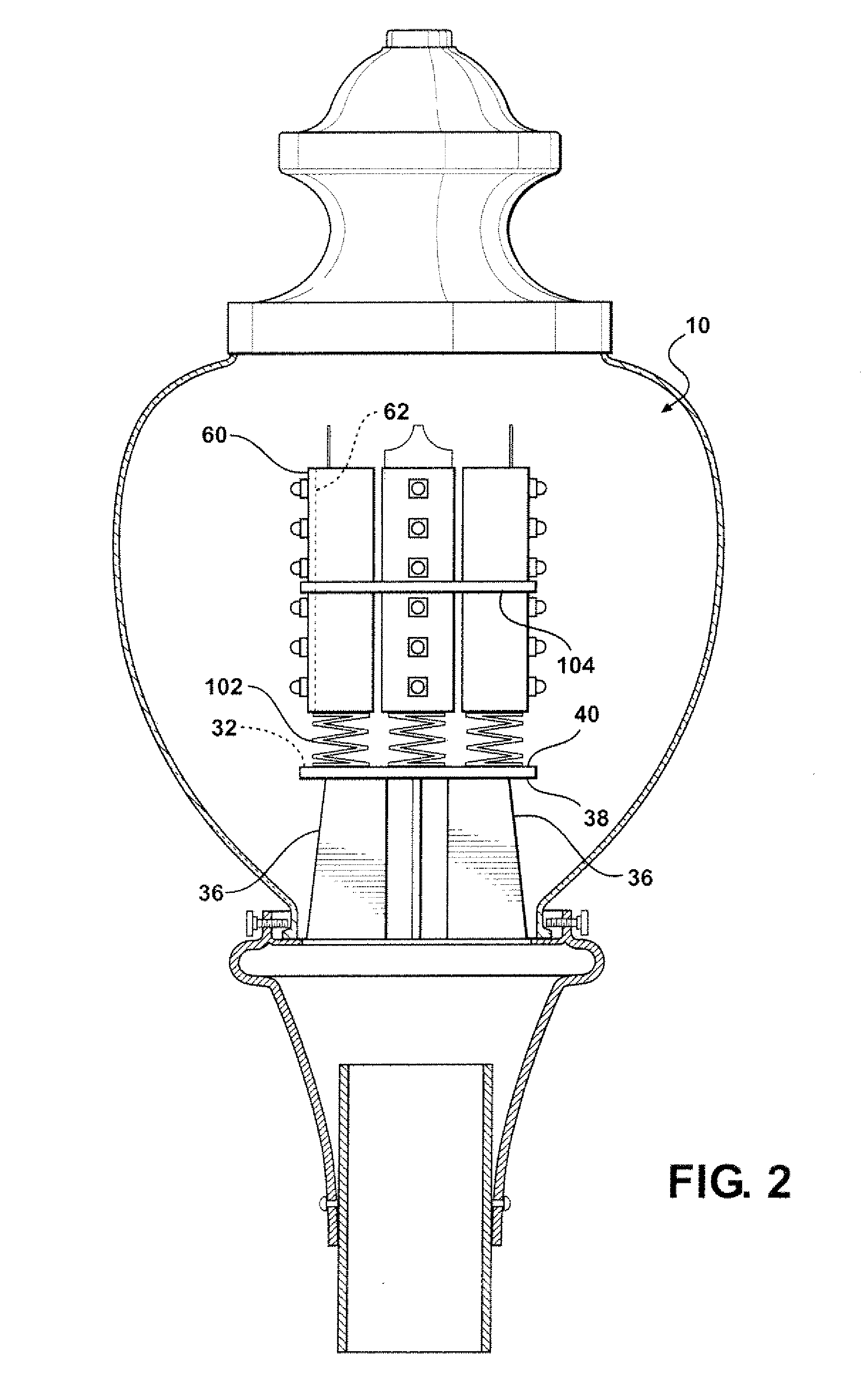
[0018]Referring to the Figures, a light emitting assembly 20 for insertion through a narrow opening 22 in a globe 24 is generally shown. The light assembly 20 comprises a base 26, generally indicated, which typically includes a bottom flange 28 for engaging the narrow opening 22 of the globe 24. The base 26 preferably includes a plurality of base sides 30 extending into the globe 24 to an upper periphery 32 of a polygonal cross-section. The bottom flange 28 connects the base 26 to the globe 24 and secures the base 26 in a stable positive within the globe 24.

[0019]In one embodiment, the base 26 comprises a plate 34 and a plurality of legs 36 extending transversely from the bottom surface 38 of the plate 34, as shown in FIG. 1. The plate 34 has a top surface 40 extending continuously within the upper periphery 32, a bottom surface 38, and the base sides 30 defining the polygonal cross section. The legs 36 are preferably spaced around the plate 34 adjacent the base sides 30. In the emb...


PUM


Abstract

An L.E.D. light emitting assembly (20) includes a heat sink (50) defined by independent elongated sections (52) upwardly from a base (26) in parallel relationship. L.E.D.s (72) are disposed on a mounting surface (60) and fins (64) are disposed on a heat transfer surface (62) of the elongated sections (52). The elongated sections (52) and base (26) are pivotably connected at a hinge (86). The hinge (86) can include a spring (102). A spreader (90) can pivot the elongated sections (52) about the hinge (86). A flexible stop (106) with a resilient tip (110) is attached to top ends (58) of the elongated sections (52). The elongated sections (52) are held together by a retainer (88), such as a band (104), and inserted through a narrow opening (22) of a globe (24). A deployment mechanism (84) moves the elongated sections (52) to a non-parallel position to fill the globe (24).

Description

CROSS REFERENCE TO RELATED APPLICATION[0001]This application claims the benefit of provisional application Ser. No. 61 / 086,846 filed Aug. 7, 2008.BACKGROUND OF THE INVENTION[0002]1. Field of the Invention[0003]The subject invention relates to a light emitting assembly of the type including light emitting diodes (L.E.D.s), and more particularly, light assemblies for insertion into a globe.[0004]2. Description of the Prior Art[0005]For over a century, municipalities have used transparent globes, such as an “Acorn” or “Type 118” luminaire to enclose and protect street light assemblies. In addition to providing protection, transparent globes are chosen over other protective covers for their appealing ornamental design. The globe is disposed around the light assembly by inserting the light assembly through a narrow opening in the bottom of the globe. Typically, in existing globes, a high-intensity discharge (H.I.D.) light bulb or a light assembly including H.I.D. lights moves into the na...

Claims


Application Information

Patent Timeline
IPC IPC(8): F21S4/00H01J9/00
CPCF21K9/00F21S8/088F21V17/04F21V19/04F21V29/004F21V29/89F21Y2101/02F21V19/003F21V29/75F21V29/77F21V29/777F21W2131/103F21Y2115/10F21V29/74F21V29/76
Inventor HOCHSTEIN, PETER A.WOLGAMOTT, MELVIN L.
Owner RELUME TECH
Why Eureka
Try Eureka