Walking assistance device

a technology of assistance device and hip joint, which is applied in the field of walking assistance device, can solve the problems of increasing the inertia mass of the knee of the wearer, increasing the power consumption of increasing so as to increase the inertia mass of the knee joint, and the load on the hip joint electric motor becomes less

Inactive Publication Date: 2010-02-11
HONDA MOTOR CO LTD
View PDF3 Cites 77 Cited by
  • Summary
  • Abstract
  • Description
  • Claims
  • Application Information

AI Technical Summary

Benefits of technology

[0024]According to the walking device of the present invention, as the knee joint power generator is disposed at a position corresponding to a side part of the hip joint of the wearer along with the hip joint power generator instead of a position corresponding to the knee joint, the load on the hip joint electric motor becomes less as compared to when the knee joint electric motor is disposed on the knee. In addition, the increase in the inertia mass of the knee joint which would be caused if the knee joint power generator were disposed on the knee joint can be avoided, thereby preventing the walking sense of the wearer from being hampered by such increase in the knee joint inertia mass. This achieves appropriate walking assistance while reducing the discomfort that the wearer may feel. Moreover, since the knee joint power generator is disposed near body trunk on a side part of the hip joint, where the amount of the displacement with respect to the body trunk is significantly small during walking, it will not be displaced significantly by walking, and thus the load caused by the inertia moment of the knee joint can be prevented from being increased by the displacement of the knee joint power generator.

Problems solved by technology

In the above-mentioned walking assistance device, as the knee joint electric motor is disposed on the knee joint, the hip joint electric motor rotates the thigh support member along with the knee joint electric motor, and thus the load on the hip joint electric motor increases, thereby increasing its power consumption.
In addition, if the electric motor, which is a heavy load, is disposed on the knee joint whose movement range is broad, the inertia mass of the knee of the wearer increases, thereby hampering the natural walking sense and disrupting the walking pace of the wearer.

Method used


Image

  • Walking assistance device
  • Walking assistance device
  • Walking assistance device

Examples


Embodiment Construction

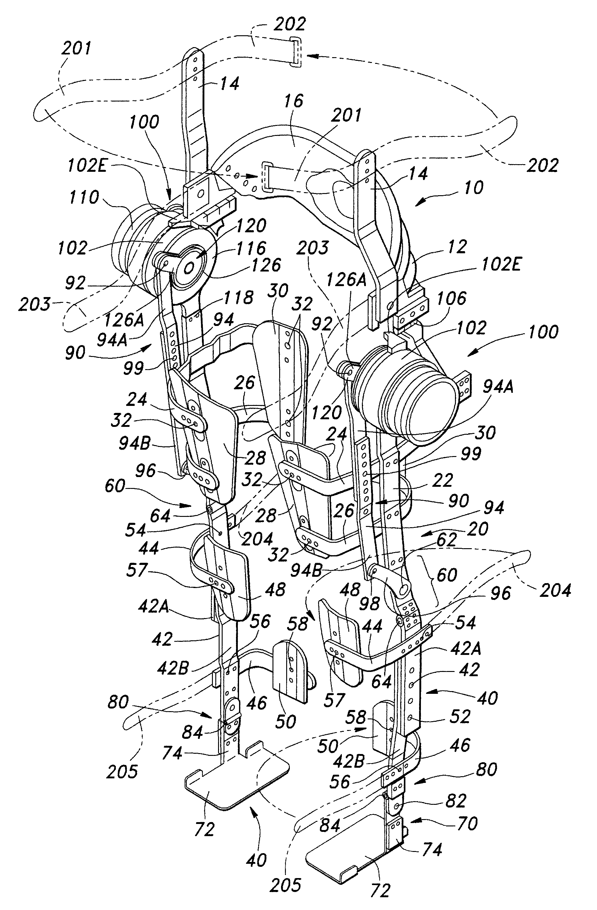
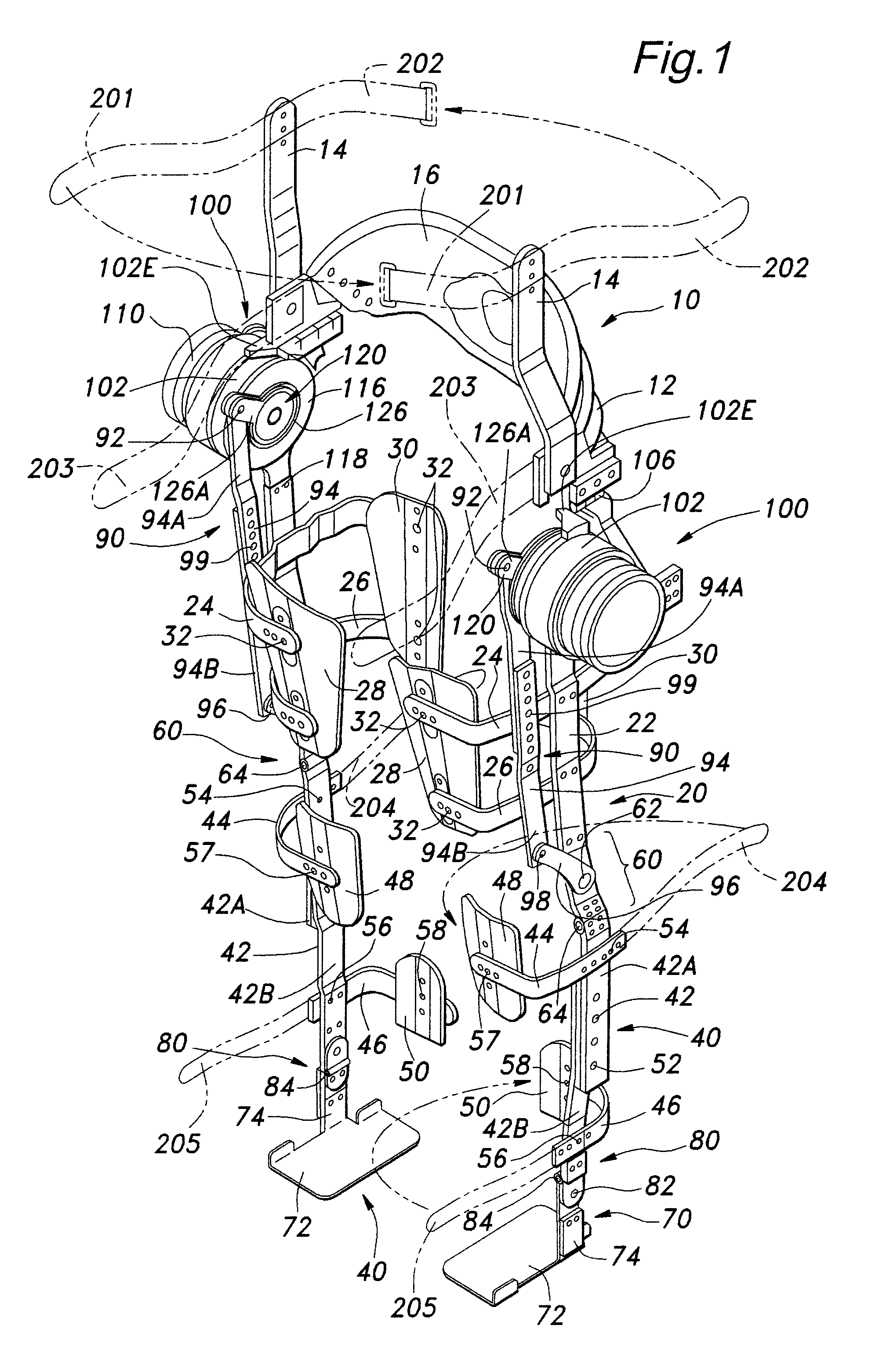
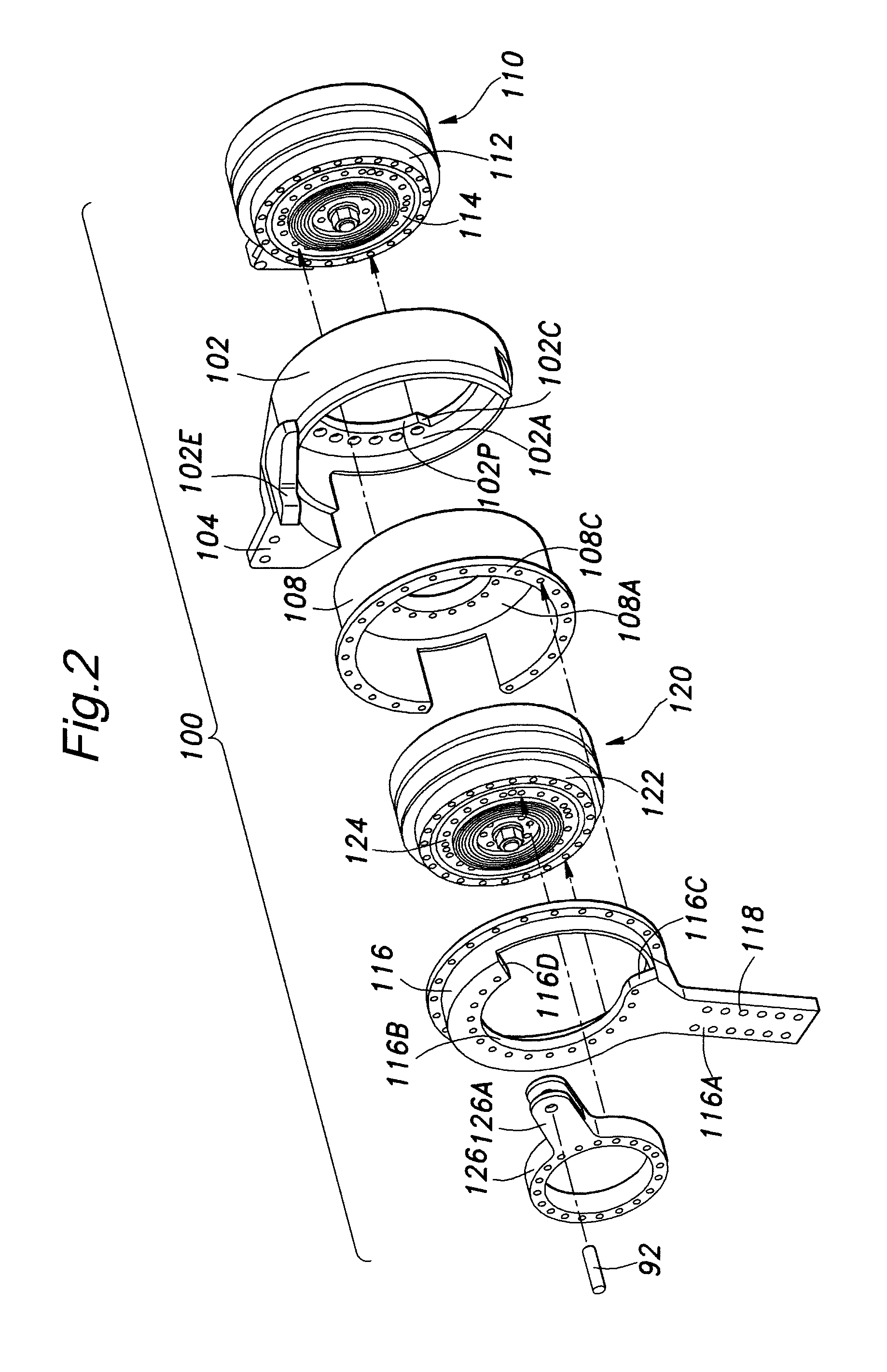
[0031]An embodiment of the walking assistance device according to the present invention is described below in detail with reference to FIGS. 1-4.

[0032]As shown in FIG. 1, the walking assistance device of this embodiment mainly comprises a pelvis support member 10 adapted to be worn on the pelvis of the wearer, right and left thigh support members 20 adapted to be worn on the right and left thighs of the wearer, right and left leg support members 40 adapted to be worn on the right and left legs of the wearer, right and left knee joint hinges 60 disposed at positions corresponding to side parts of the right and left knee joints of the wearer and connecting the leg support members 40 to the thigh support members 20 in a manner that enables back-and-forth rotation of the leg support members 40 with respect to the thigh support members 20, right and left foot support members 70 adapted to support the feet of the wearer, and right and left foot joint hinge 80 disposed at positions corresp...


PUM


Abstract

The present invention provides a walking assistance device comprising a pelvis support member (10) adapted to be worn on a hip of a wearer; a thigh support member (20) adapted to be worn on a thigh of the wearer; a leg support member (40) adapted to be worn on a leg of the wearer; a knee joint hinge (60) disposed at a position corresponding to a side part of a knee of the wearer and connecting the leg support member (40) to the thigh support member (20) in a manner that enables back-and forth rotation of the leg support member (40) with respect to the thigh support member (20); and a power generator assembly (100) mounted to the pelvis support member (10) at a position corresponding to a side part of a hip joint of the wearer; wherein the power generator assembly (100) comprises a hip joint power generator (110) and a knee joint power generator (120) each having an output member (116, 126, respectively), with the output member (116) of the hip joint power generator (110) being connected to the thigh support member (20) in a power-transmittable manner and the output member (126) of the knee joint power generator (120) being connected to the leg support member (40) via a power transmitting mechanism (90) which transmits power generated by the knee joint power generator (120) to the leg support member (40).

Description

TECHNICAL FIELD[0001]The present invention relates to a walking assistance device, especially to a walking assistance device for assisting a person with impaired motor function of lower limbs in walking.BACKGROUND OF THE INVENTION[0002]There is known a walking assistance device for assisting a person with impaired motor function of the lower limbs, caused by lesion or advanced age, in walking, comprising a pelvis support member adapted to be worn on a pelvis of a wearer, a thigh support member adapted to be worn on a thigh of the wearer, a leg support member adapted to be worn around a leg of the wearer, a knee joint hinge disposed at a position corresponding to a side part of a knee of the wearer and connecting the leg support member to the thigh support member in a manner that enables back-and-forth rotation of the leg support member with respect to the thigh support member, a hip joint electric motor disposed at a position corresponding to a side part of a hip joint of the wearer...

Claims


Application Information

Patent Timeline
Patent Type & Authority Applications(United States)
IPC IPC(8): A61F5/00
CPCA61F5/0102A61H2201/1676A61H2201/5007A61H2201/5061A61H2201/14A61H1/0255A61H3/00A61H2201/0192A61H2201/1215A61H2201/1623A61H2201/163A61H2201/164A61H2201/1642A61H2201/165A61H3/008
Inventor SHIMADA, KEIYASUHARA, KEN
Owner HONDA MOTOR CO LTD
Why Eureka
Try Eureka