Portable tool and method of using a portable powered tool

a portable, powered tool technology, applied in the field of portable powered tools, can solve the problems of reducing the degree of control of the user, tool suffering from the limitation that it is designed, and user may be prone to fatiguing

Inactive Publication Date: 2010-02-18
ECHO INCORP
View PDF30 Cites 5 Cited by
  • Summary
  • Abstract
  • Description
  • Claims
  • Application Information

AI Technical Summary

Benefits of technology

[0018]The invention is directed to a portable powered tool having an elongate housing with a central axis, a working component on the elongate housing, a drive for the working component on the elongate housing and having different states, and a control with a grip. The grip is configured to be grasped by a user by extending the user's one hand at least partially around the grip and thereby the central axis of the elongate housing to thereby situate the user's one hand in an operating position. The user's one hand, grasping the grip in the operating position, is usable to: (a) support and reposition the portable powered tool; and (b) move the grip around the central axis of the elongate housing to change the state of the drive.

Problems solved by technology

Thus, after extended use, the user may be prone to fatiguing.
This also may lead to fatigue and may additionally diminish the degree of control that the user has as he / she attempts to precisely place the working component of the tool during an operation.
Further, this tool suffers from the limitation that it is designed to be held by a user in essentially one orientation.
Field conditions may require that a user awkwardly change the orientation from that for which it is designed.
In the former case, the ability to comfortably support the tool and at the same time properly operate the throttle may be compromised.
This could lead to user fatigue and, potentially to an injury, if appropriate safeguards are not taken.

Method used


Image

  • Portable tool and method of using a portable powered tool
  • Portable tool and method of using a portable powered tool
  • Portable tool and method of using a portable powered tool

Examples


Embodiment Construction

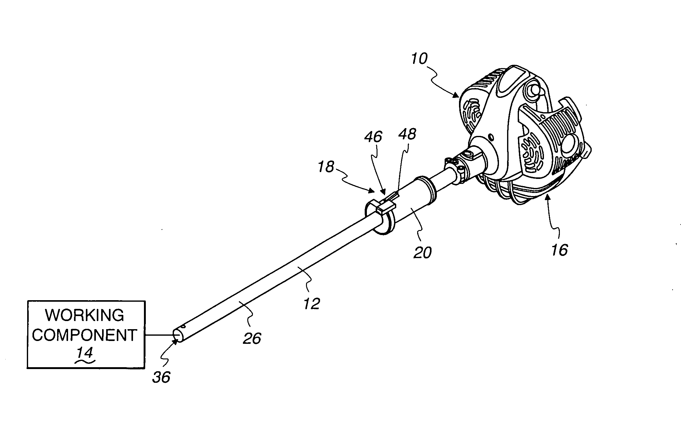
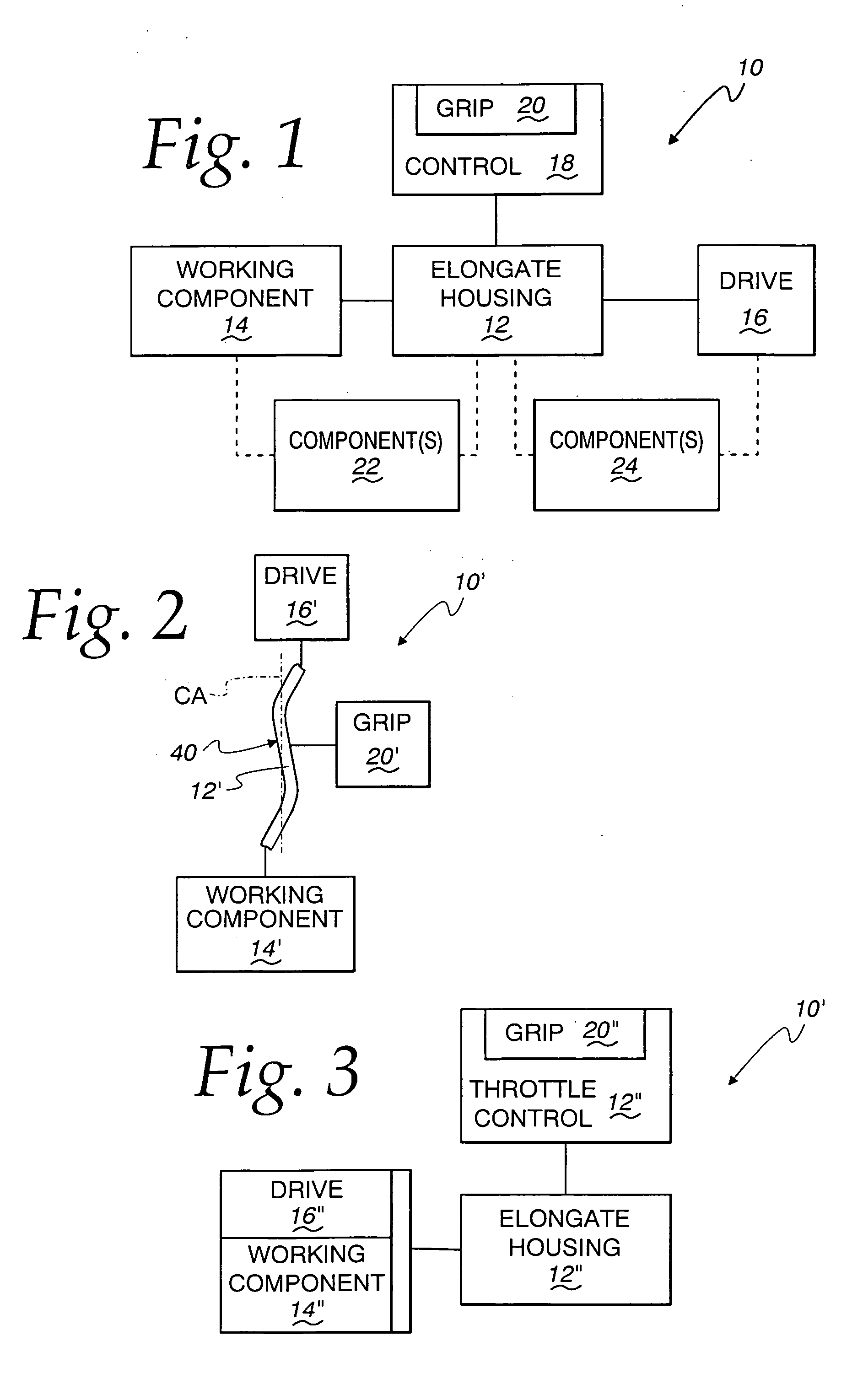
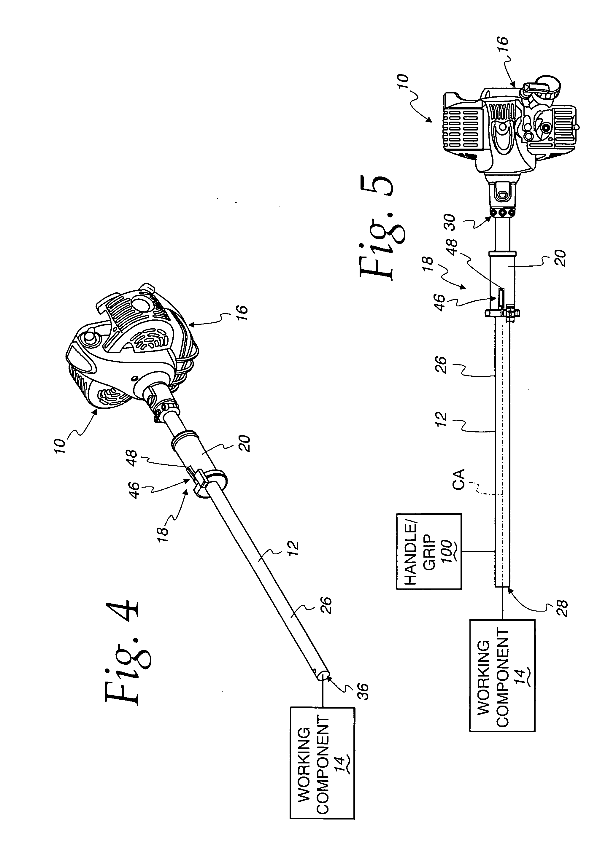
[0049]A portable, powered tool, according to the invention, is shown schematically at 10 in FIG. 1. The powered tool 10 has an elongate housing 12 with a central axis. A working component 14 is provided on the elongate housing 12. A drive 16 for the working component 14 is additionally provided on the elongate housing 12 and has different states. A control 18 is also provided on the elongate housing 12 and has a grip 20 that is configured to be grasped by a user by extending one hand of the user at least partially around the grip 20, and thereby the central axis of the elongate housing 12, to thereby situate the user's one hand in an operating position. The user's one hand grasping the grip 20 in the operating position is usable to: (a) lift, support and reposition the portable powered tool 10; and (b) move the grip 20 around the central axis of the elongate housing 12 to change the state of the drive 16.

[0050]The components are shown in schematic form in FIG. 1 since virtually a li...


PUM

PropertyMeasurementUnit
operating forceaaaaaaaaaa
flexibleaaaaaaaaaa
speedsaaaaaaaaaa

Abstract

A portable powered tool having an elongate housing with a central axis, a working component on the elongate housing, a drive for the working component on the elongate housing and having different states, and a control with a grip that is configured to be grasped by a user by extending a user's one hand at least partially around the grip and thereby the central axis of the elongate housing to thereby situate the user's one hand in an operating position. The user's one hand, grasping the grip in the operating position, is usable to: a) support and reposition the portable powered tool; and b) move the grip around the central axis of the elongate housing to change the state of the drive.

Description

BACKGROUND OF THE INVENTION[0001]1. Field of the Invention[0002]This invention relates to portable, powered tools and, more particularly, to a tool having an elongate housing that is engageable and repositionable by a user to controllably situate a working component at an end of the housing.[0003]2. Background Art[0004]There is a multitude of portable, powered tools that are built around an elongate housing through which a user can extend the reach of a working component at an end of the housing. This tool design is common in the landscaping industry, for which tools are offered with many different capabilities. For example, the working component may incorporate a rotary, flexible trimmer line, an endlessly moving cutting chain, a reciprocating brush cutting blade(s), etc.[0005]The elongate housing may be made with a fixed length or a variable length, with the latter commonly achieved through a telescoping connection of housing parts. With the tool incorporating a rotary flexible tr...

Claims


Application Information

Patent Timeline
Patent Type & Authority Applications(United States)
IPC IPC(8): B23B45/00B27B19/00B26B15/00
CPCA01D34/90B27B17/0008B23D47/00
Inventor NEMCEK, ANDREWCARLSON, RONALD
Owner ECHO INCORP
Why Eureka
Try Eureka