Attachment Apparatus for Studio Equipment and the Like

a technology for attaching equipment and studio equipment, applied in the direction of lighting and heating equipment, lighting support devices, furniture parts, etc., can solve the problems of not being able to function outside the position, and being disadvantageous to individuals who require flexibility in setting up audio or video equipment, so as to achieve flexible mounting applications and efficient support of microphones

Inactive Publication Date: 2010-02-18
QUICKLIP
View PDF17 Cites 18 Cited by
  • Summary
  • Abstract
  • Description
  • Claims
  • Application Information

AI Technical Summary

Benefits of technology

[0006]The mounting bracket comprises a pair of opposing support clips, or clamping members, pivotally attached to a connecting means, such as an adjustment screw with a pin, a spring and a circular body (“body”) with a tapered end and a threaded end. The tapered end of the body provides an interface to accept the adjustment screw, which serves as a connecting means between the circular body and support clips. The support clips pivotally attach to the adjustment screw. One end of each support clip slidably engages the tapered end of the body, while the other end of the pair of clips act as jaws that clamp about a support structure. The threaded end of the body provides an interface for a conventional microphone holder to attach to the mounting bracket.
[0007]In operation, the user rotates the body while the support clips and adjustment screw are held stationary. The adjustment screw and slidable ends of the support clips raise or lower in relation to the tapered end of the body. This action causes the jaws of the support clips to open or close respectively. The spring biases the support clips open as the body is rotated to extend the adjustment screw.
[0008]To use the mounting bracket, the user screws the threaded end of the body onto a conventional microphone holder. The user then rotates the body in a right-to-left direction while holding the support clips and adjustment screw stationary. The adjustment screw extends in relation to the body. The ends of the support clips travel upwardly along the tapered end causing the jaws to open. The spring biases the jaws open so the jaws may engage a support structure, such as the rail of a typical drop ceiling. Once the jaws are in position to engage the support structure, the user rotates the body in a left-to-right direction, which retracts the adjustment screw into the body. The ends of the support clips travel downwardly along the tapered end, causing the jaws to close about the support structure. After the mounting bracket securely attaches to the support structure, the microphone slidably attaches to the microphone holder. The microphone is securely attached to a support structure, which, in the absence of a mounting bracket of this invention, may not have been usable to efficiently support the microphone.
[0009]In one embodiment, the mounting bracket may attach a microphone to almost any support structure up to one inch in width or diameter. In an alternate embodiment, the mounting bracket may attach a microphone to almost any support structure up to two inches in width or diameter. In either embodiment, the mounting bracket has the capability of attaching to uniform or non uniform objects such as trees, poles, drop ceilings, pipes, doors, handles and knobs, to name just a few typical examples.
[0010]Accessories, desirably integrated into a kit of this invention, are designed specifically to cooperate with the mounting bracket to be even more versatile in its mounting applications. The accessories are: a desktop (desk stand) plate, a light stand (portable light adapter), a camera mounting adapter, universal joint (adjustable mounting bracket), drop ceiling light assembly, and a hook. The desk stand plate assembly allows a microphone to be positioned on a flat surface, such as a desk, when no other object is available on which the mounting bracket may clamp. The plate assembly has a weighted flat base and an integrated support, such as a tee (“T”) or channel mount (“U”) on to which the mounting bracket may clamp.
[0011]The shoe mount adapter of this invention allows users to attach a microphone to a video camera or other piece of video equipment. This adapter attaches to the shoe mount of the video equipment, and the mounting bracket clamps to the adapter.

Problems solved by technology

However, most brackets are designed for only one mounting position and cannot function outside that position.
This fact is particularly disadvantageous to the individual who requires the flexibility to set up audio or video equipment in various “field” settings.

Method used


Image

  • Attachment Apparatus for Studio Equipment and the Like
  • Attachment Apparatus for Studio Equipment and the Like
  • Attachment Apparatus for Studio Equipment and the Like

Examples


Embodiment Construction

[0090]Embodiments of the invention shown in the accompanying drawings are now described in detail. They exemplify and teach those skilled in the art how to make and use the inventive concepts described above and recited in the claims appended below.

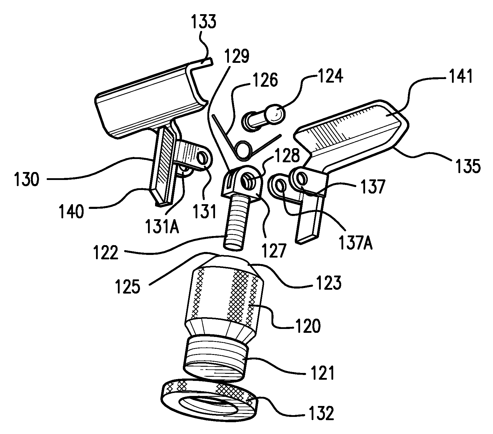
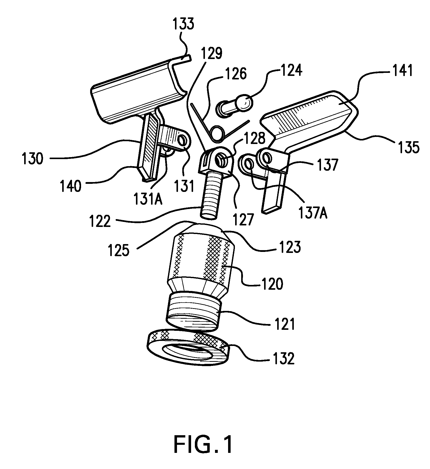
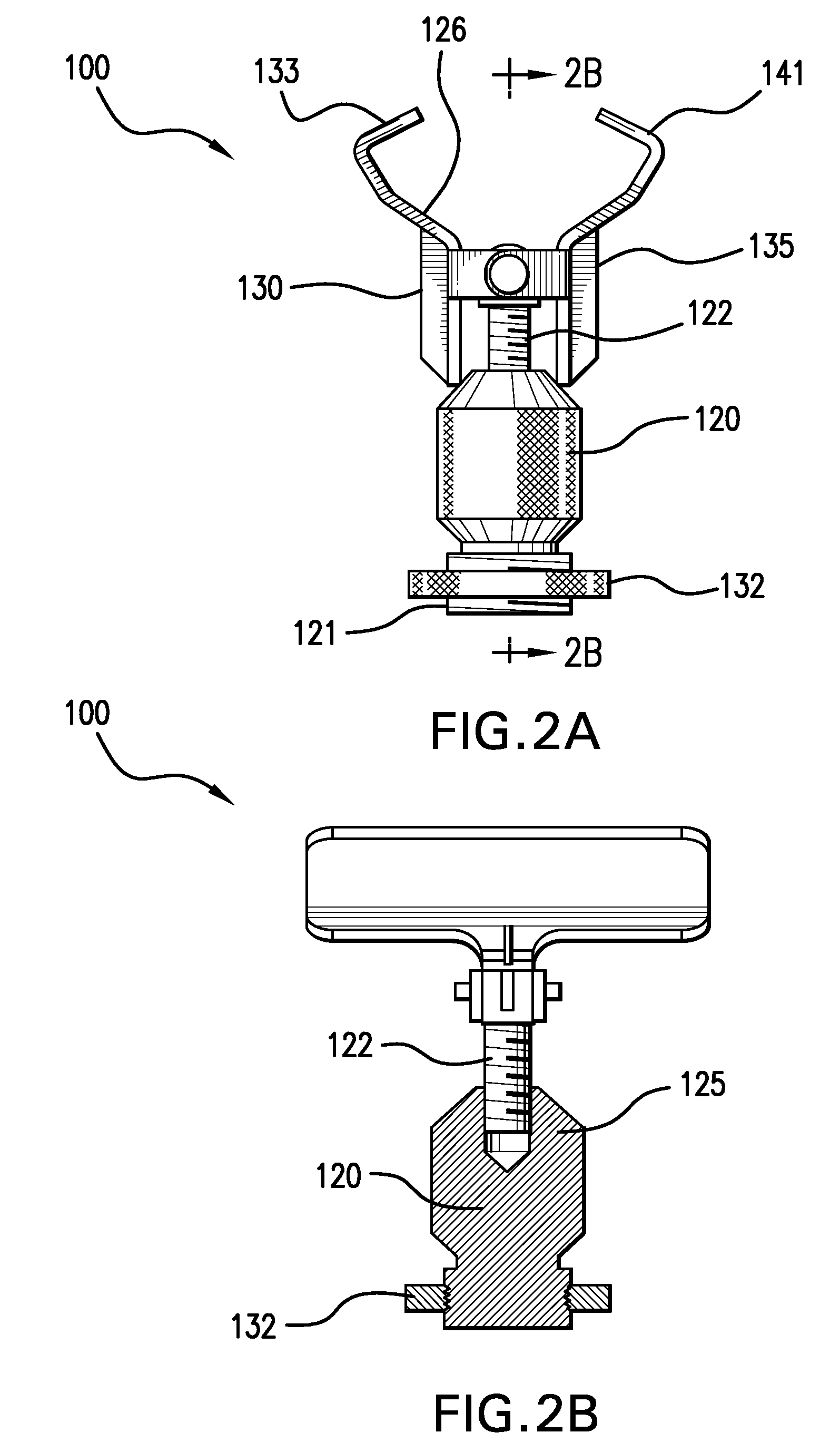
[0091]FIGS. 1 and 2 illustrate the elements that comprise the mounting bracket 100, adapted for mounting a microphone on almost any object up to, e.g., two inches in diameter. The mounting bracket 100 includes a circular body 120, having a threaded end 121, for receiving a microphone holder, and a tapered end 123, a threaded adjustment screw 122, a set pin 124, a spring 126, and two support clips 130 and 135, each with a jaw 133 and 141 respectively for attaching the mounting bracket 100 to a support structure. The foundation of the mounting bracket 100 is the body 120 with a tapered end 123.

[0092]In one embodiment, the “light-duty” embodiment, the overall length of body 120 is approximately 1¼ inch long, and at its widest point, ¾ inch i...


PUM


Abstract

Mounting brackets for mounting microphones, lights, video, audio and photographic tools and accessories utilized in the audio/video industry to a variety of support structures or fixtures. This invention provides quick and effective attachment of numerous audio/video devices and other paraphernalia onto a wide variety of fixtures. Convenient clamping and mounting mechanisms are disclosed, as well as a kit of such mechanisms.

Description

FIELD OF THE INVENTION[0001]This invention relates to mounting brackets for mounting microphones, lights, video, audio and photographic tools and accessories utilized in the audio / video industry to a variety of support structures or fixtures.BACKGROUND OF THE INVENTION[0002]Numerous mounting brackets and holders exist to provide mounting of video and / or audio equipment to a support structure. However, most brackets are designed for only one mounting position and cannot function outside that position. This fact is particularly disadvantageous to the individual who requires the flexibility to set up audio or video equipment in various “field” settings. I perceive the need for a versatile mounting bracket that makes it easy for such equipment to be quickly mounted to almost any object in any location.SUMMARY OF THE INVENTION[0003]In one aspect of the present invention, a mounting device for microphones, lights, video, audio, and photographic tools and accessories is provided, with the ...

Claims


Application Information

Patent Timeline
Patent Type & Authority Applications(United States)
IPC IPC(8): A47B96/07
CPCH04R1/026F21V21/048F21V21/088H04R1/083
Inventor RUSSELL, CLIVE
Owner QUICKLIP
Why Eureka
Try Eureka