Fuel-cascaded fuel cell stacks with decoupled power outputs

a fuel cell and cascade technology, applied in the direction of fuel cells, electrochemical generators, electrical equipment, etc., can solve the problems of irreversible cell corrosion, concomitant performance reduction, fuel starvation, etc., and achieve 100% fuel utilization, high fuel utilization, and minimal consequences of resulting fuel starvation

Inactive Publication Date: 2010-02-18
AUDI AG
View PDF6 Cites 6 Cited by
  • Summary
  • Abstract
  • Description
  • Claims
  • Application Information

AI Technical Summary

Benefits of technology

[0005]Disclosed features include: PEM fuel cell power plants having high fuel utilization with minimal consequences from resulting fuel starvation; a fuel cell power plant achieving substantially 100% fuel utilization with minimal risk of fuel starvation in a main fuel cell stack that powers a main load; improved efficiency of PEM fuel cell power plants; improved avoidance of fuel starvation in PEM fuel cell power plants; and improved avoidance of the consequences of fuel starvation in high utilization, PEM fuel cell power plants.

Problems solved by technology

If a fuel cell power plant is run near 100% fuel utilization, any increased load transitions requiring more fuel will cause fuel starvation, at least at some portion of some of the fuel cells in the power plant.
Such fuel starvation leads to irreversible cell corrosion and concomitant reduction in performance.
While this does achieve higher fuel utilization with low risk of fuel starvation, the recycle blowers are costly, consume power, are unreliable and have freeze tolerance issues.
Ejectors usually have limited design ranges of operation, so that a single ejector is unlikely to perform at the full range of fuel utilizations, from idle to full power.
However, it is difficult to operationally control cascaded stacks in a robust and durable manner, while maintaining high overall utilizations in the presence of transient power demands.

Method used


Image

  • Fuel-cascaded fuel cell stacks with decoupled power outputs
  • Fuel-cascaded fuel cell stacks with decoupled power outputs
  • Fuel-cascaded fuel cell stacks with decoupled power outputs

Examples


Embodiment Construction

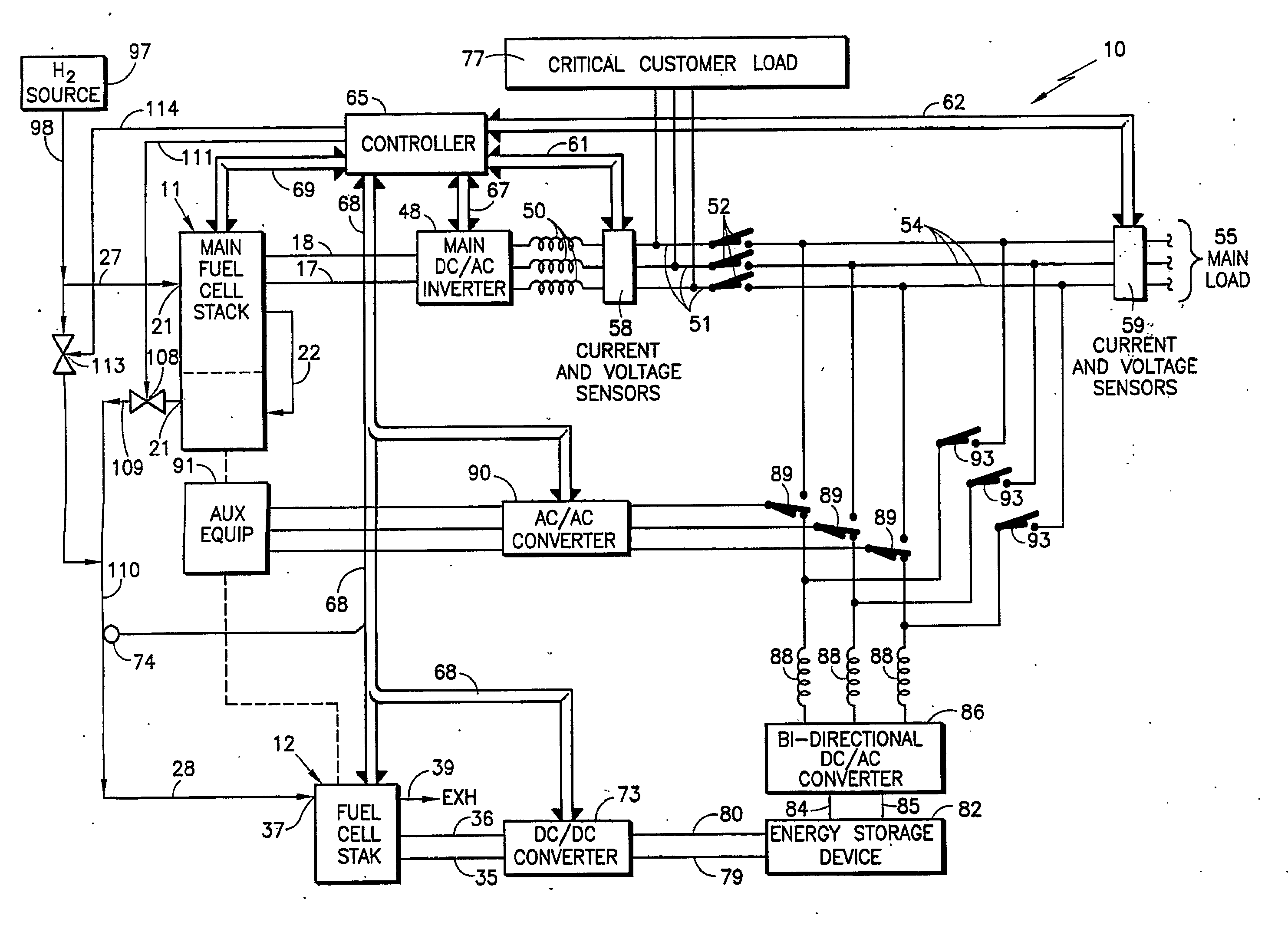
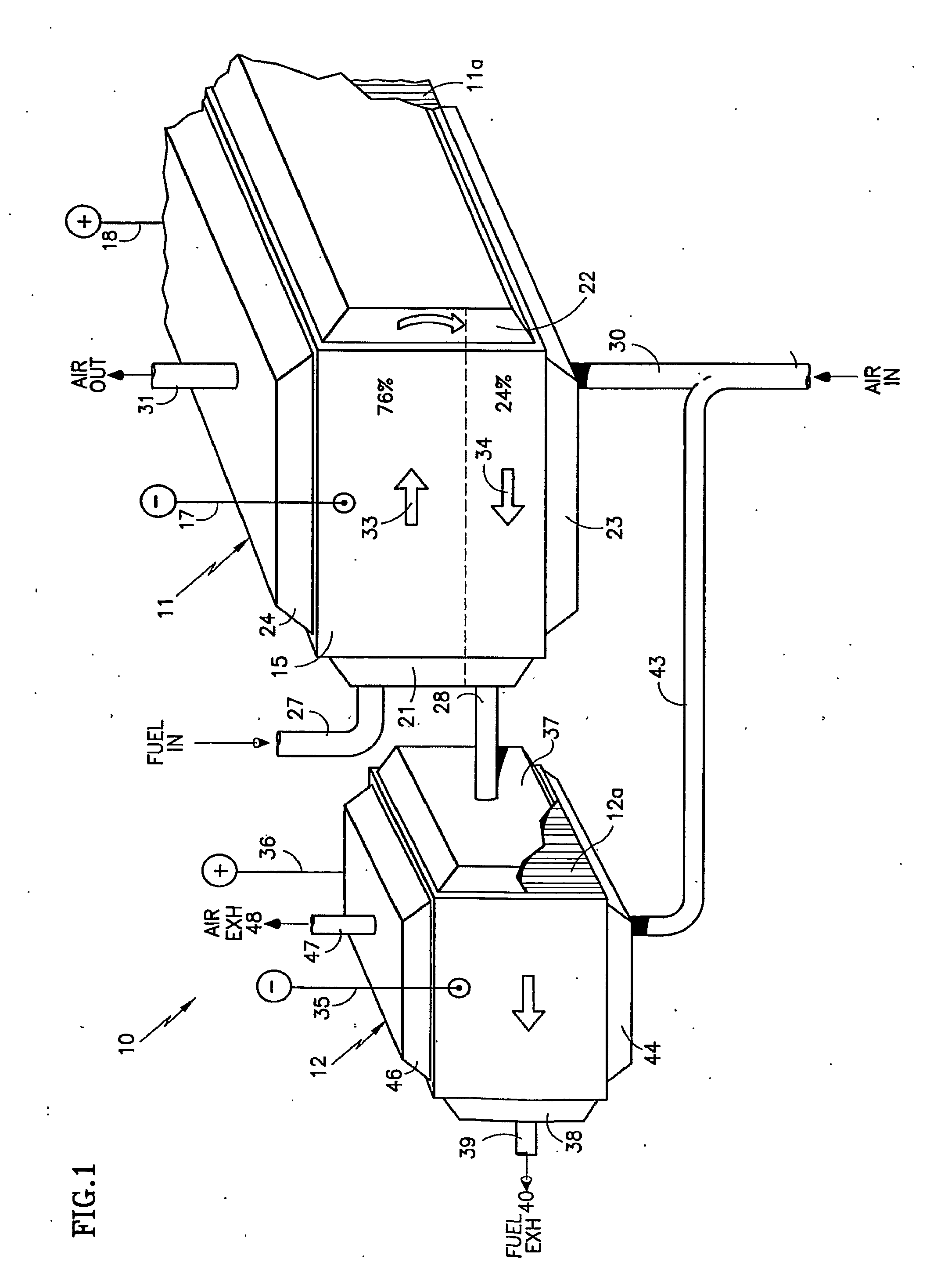
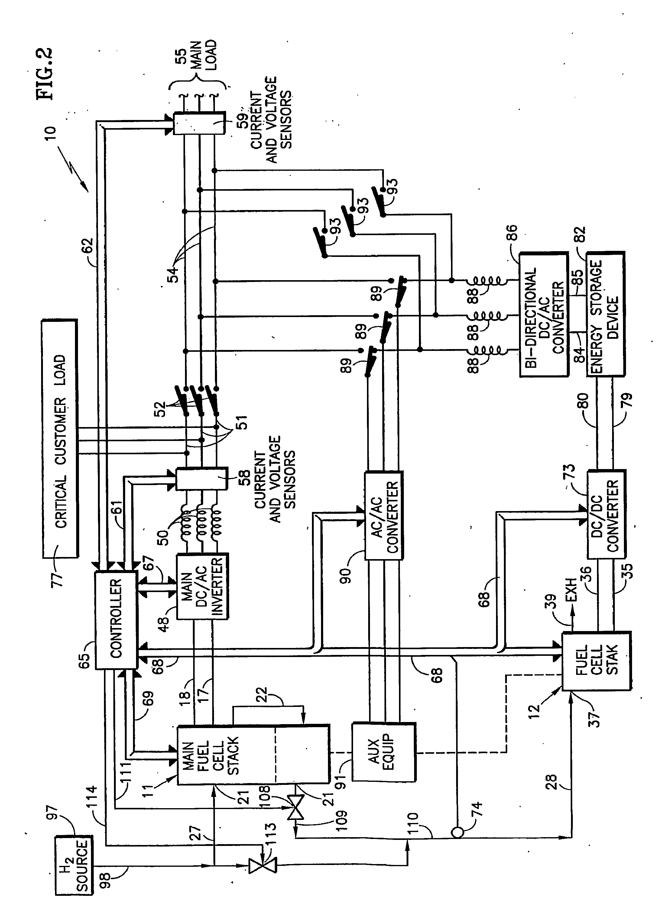
[0016]In FIG. 1, a fuel cell power plant 10 includes a primary stack 11 of fuel cells 11a and a secondary stack 12 of fuel cells 12a. The stack 11 has power take-off elements 17, 18 which may be integrated with end plates (not shown). The primary stack has a fuel inlet / outlet manifold 21, a fuel turn manifold 22, an air inlet manifold 23, and an air exit manifold 24. Fuel enters through a fuel inlet conduit 27 and exits through a fuel transfer conduit 28. Air enters through an air inlet conduit 30 and exits through an air exit conduit 31.

[0017]As an example only, the fuel reactant gas flow field plates of each of the fuel cells 11a in the stack 11 as well as the fuel inlet / outlet manifold 21 are set up so that 76% of each fuel cell receives fuel in a first pass indicated by an arrow 33, and 24% of each fuel cell receives fuel in a second pass indicated by an arrow 34. In this example, the main stack 11 may comprise, for instance, 32 fuel cells. The output voltage in such a case woul...


PUM

PropertyMeasurementUnit
output voltageaaaaaaaaaa
voltageaaaaaaaaaa
series voltage relationshipaaaaaaaaaa

Abstract

Fuel exhaust (109) of a primary fuel cell stack (11) flows into an auxiliary fuel cell stack (12) which powers a DC storage (82) feeding a bi-directional DC/AC converter (86) that is switchable (89) to auxiliary equipment (90, 91) (such as pumps) to a main power bus (54) feeding a main load (55). Fresh fuel (97) is provided (98, 105) to the primary stack for 90% fuel utilization, with over 99% overall power plant fuel utilization. The auxiliary equipment (90, 91) may be powered by the bus (54).

Description

TECHNICAL FIELD [0001]This disclosure relates to cascaded fuel cell stacks, the second stack receiving the anode effluent of the first stack as its fuel, to achieve about 99% overall fuel utilization with below 70% utilization of fuel through each pass of the first stack. The power output of the two fuel cells are decoupled to achieve different voltages, to be able to serve different loads or the same load, and to require hydrogen starvation protection in only the second fuel cell stack in the cascade, which may be much smaller than the first fuel cell stack.BACKGROUND ART [0002]Proton exchange membrane (PEM) fuel cell power plants should achieve close to 99% overall fuel utilization in order to be economical, to reduce fuel discharge to ambient, and to reduce minimum fuel storage requirements, particularly in vehicular applications. If a fuel cell power plant is run near 100% fuel utilization, any increased load transitions requiring more fuel will cause fuel starvation, at least a...

Claims


Application Information

Patent Timeline
Patent Type & Authority Applications(United States)
IPC IPC(8): H01M8/04
CPCH01M8/04029H01M8/04089H01M8/04462H01M8/04559H01M8/04589Y02E60/50H01M8/04761H01M8/249H01M16/003H01M2008/1095H01M8/04753
Inventor RAMASWAMY, SITARAMSTEINBUGLER, MARGARET M.VAN DINE, LESLIE L.
Owner AUDI AG
Why Eureka
Try Eureka