
Dental implant assembly

a technology for dental implants and assembly, applied in dental implants, dental surgery, medical science, etc., can solve the problems of implant requiring a surgical operation that is often undesirable, plastic deformation and micro welds at the mating surface, etc., and achieve the effect of convenient assembly and disassembly, and accurate and tight fi

Active Publication Date: 2022-02-10
NOVODENT SA
View PDF0 Cites 0 Cited by
  • Summary
  • Abstract
  • Description
  • Claims
  • Application Information

AI Technical Summary

Benefits of technology

The invention is a dental implant assembly that can accurately fit an abutment and implant together, making it easy to assemble and disassemble. Additionally, it allows for adjustment of the abutment height with minimal patient impact. This assembly is also versatile, making it cost-effective to assemble various implants to different abutments.

Problems solved by technology

The abutment is typically held in the implant with a friction fit, whereby this friction fit may cause plastic deformation and micro welds at the mating surfaces.
Removal and re-insertion of the abutment to the implant in a different rotational position may cause asperities to the formed in which bacteria may proliferate, which is of course undesirable.
Another problematic issue of implants occurs if the patient's bone or soft tissue recede and the abutment height needs to be corrected.
Removal and replacement of the implant requires a surgical operation that is often undesirable.

Method used


Image

  • Dental implant assembly
  • Dental implant assembly
  • Dental implant assembly

Examples


second embodiment

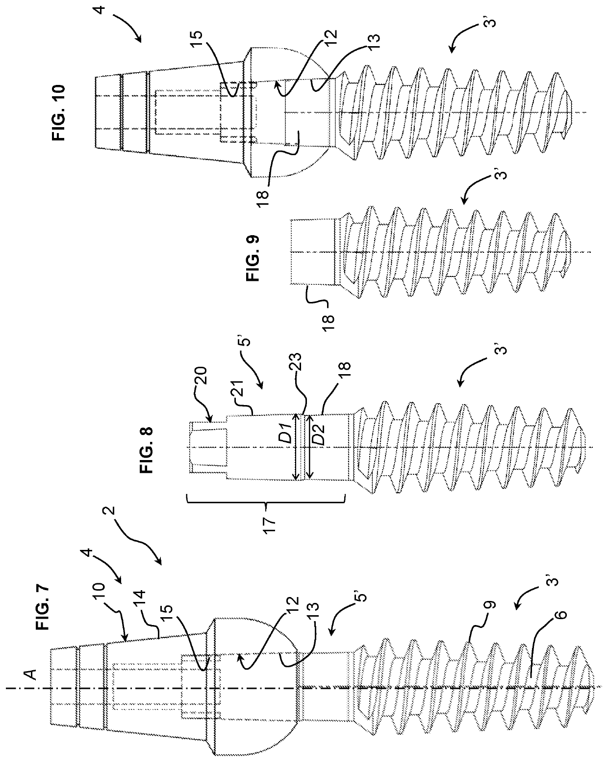
[0051]Referring now to FIGS. 7 to 10, a dental implant assembly is illustrated.

first embodiment

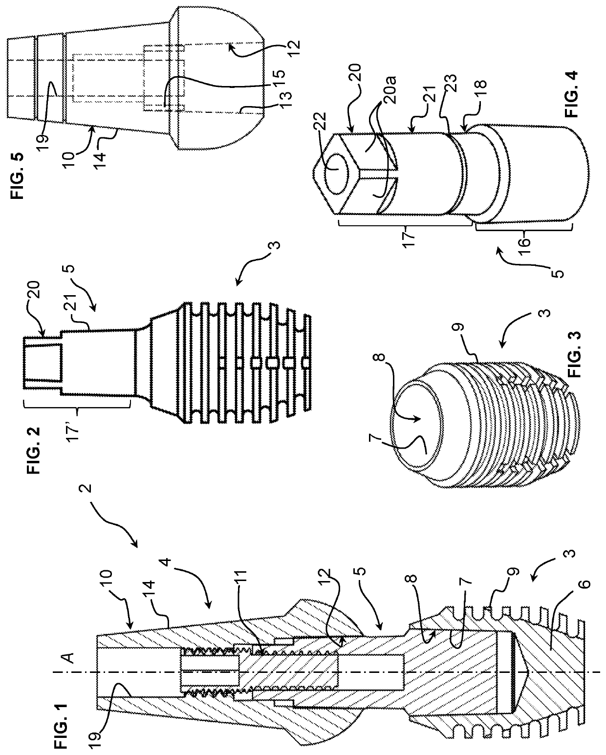
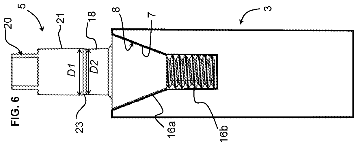
[0052]In this embodiment, the connector 5′ is integrated as a single piece with the implant 3′. The connector 5′ comprises an abutment mounting portion 17 comprising an index portion 20, an upper attachment portion 21 and a lower attachment portion 18 as described in relation to the first embodiment, and the implant 3′ comprises an outer implant surface 9, which in this embodiment is shown as a screw type implant, such screw type implant surfaces being per se known in the art.

[0053]The abutment 4 may be the same or have a similar construction as previously described for attachment to the abutment mounting portion 17 of the connector portion 5′.

[0054]As illustrated in FIG. 9 compared to FIG. 8, the connector 5′ may have an upper portion comprising the index portion 20 and the attachment portion 21 cut off in order to leave only the conical lower attachment portion 18, such procedure occurring for instance when a tooth prosthesis is replaced during the life time of the dental implant ...


PUM


Abstract

Dental implant assembly comprising an implant with a body having an outer implant surface configured for osseointegration and a connection well, and an abutment comprising a prosthesis mounting portion for assembly of a dental prosthesis thereon and a connector mounting cavity. The assembly further comprises a connector comprising an implant mounting portion for assembly in the connection well of the implant, and an abutment mounting portion for assembly in the connector mounting cavity of the abutment, the abutment mounting portion of the connector comprising an index portion and the abutment connector mounting cavity further comprising an index cavity portion for receiving the index portion therein, the index portions configured to register the rotational orientation of the abutment about a longitudinal axis (A) with respect to the connector.

Description

FIELD OF THE INVENTION[0001]The present invention relates to a dental implant assembly for mounting a dental prosthesis, such as a tooth.BACKGROUND[0002]Conventional dental implants comprise an implant that typically comprises a screw that is implanted in the bone of a patient's jaw, the implant comprising a mounting portion for subsequent mounting of an abutment onto which a dental prosthesis, in particular an artificial tooth typically made of a ceramic material, may be mounted. The implant portion is mounted initially a few weeks or months prior to the assembly of the abutment and artificial tooth in order to allow osseointegration of the implant with the jaw bone. The implant typically comprises an outer mounting surface that is serrated, or comprises a screw thread, and may have a special coating to promote osseointegration. During the fitting of the prosthesis, it is typical that the abutment needs to be removed and put back multiple times. During removal and replacement, the ...

Claims


Application Information

Patent Timeline
IPC IPC(8): A61C8/00
CPCA61C8/0069A61C8/0068A61C8/0066A61C8/006A61C8/0071
Inventor NIZAM, NEJAT
Owner NOVODENT SA
Learn More