Method of Transferring Pressure in an Articulating Surgical Instrument

a technology of transferring pressure and surgical instruments, applied in the field of remote activation of jaw members on articulating surgical instruments, can solve problems such as frustration in surgeon's efforts to position jaws

Inactive Publication Date: 2010-02-18
TYCO HEALTHCARE GRP LP
View PDF101 Cites 105 Cited by
  • Summary
  • Abstract
  • Description
  • Claims
  • Application Information

AI Technical Summary

Benefits of technology

[0011]According to another aspect of the disclosure a surgical instrument includes a handle portion near a proximal end of the surgical instrument adapted for manipulation by a user to control the surgical instrument, a tubular shaft extending distally from the handle portion and defining an instrument axis, and an end effector pivotally coupled to a distal end of the tubular shaft such that the end effector may articulate relative to the instrument axis. The end effector defines an end effector axis and includes a pair of jaw members configured to pivot about a pivot axis that is transverse to the end effector axis to move between an open and a closed configuration. The end effector also includes a force transfer member configured for longitudinal motion with respect to a fixed member in a direction along the end effector axis. The force transfer member is configured to contact at least one of the jaw members of the pair of jaw members at some lateral distance from the pivot axis and transfer a longitudinal force thereto when the pair of jaws is in the closed configuration. The end effector also includes a reactive member coupled to the fixed member and to the at least one jaw member of the pair of jaw members such that a reactionary force resulting from the force transferred to the at least one jaw member of the pair of jaw members is realized in the reactive member. The reactive member includes a pivot boss about which the at least one of the jaw members pivots.

Problems solved by technology

The closure forces typically generated by this type of procedure may present difficulties when using a typical control wire to open and close the jaws of an articulating instrument.
For example, a surgeon's efforts to position the jaws may be frustrated by a tendency for a control wire under tension to realign the jaws with the axis of the instrument after the jaws have been articulated off-axis.

Method used


Image

  • Method of Transferring Pressure in an Articulating Surgical Instrument
  • Method of Transferring Pressure in an Articulating Surgical Instrument
  • Method of Transferring Pressure in an Articulating Surgical Instrument

Examples


Embodiment Construction

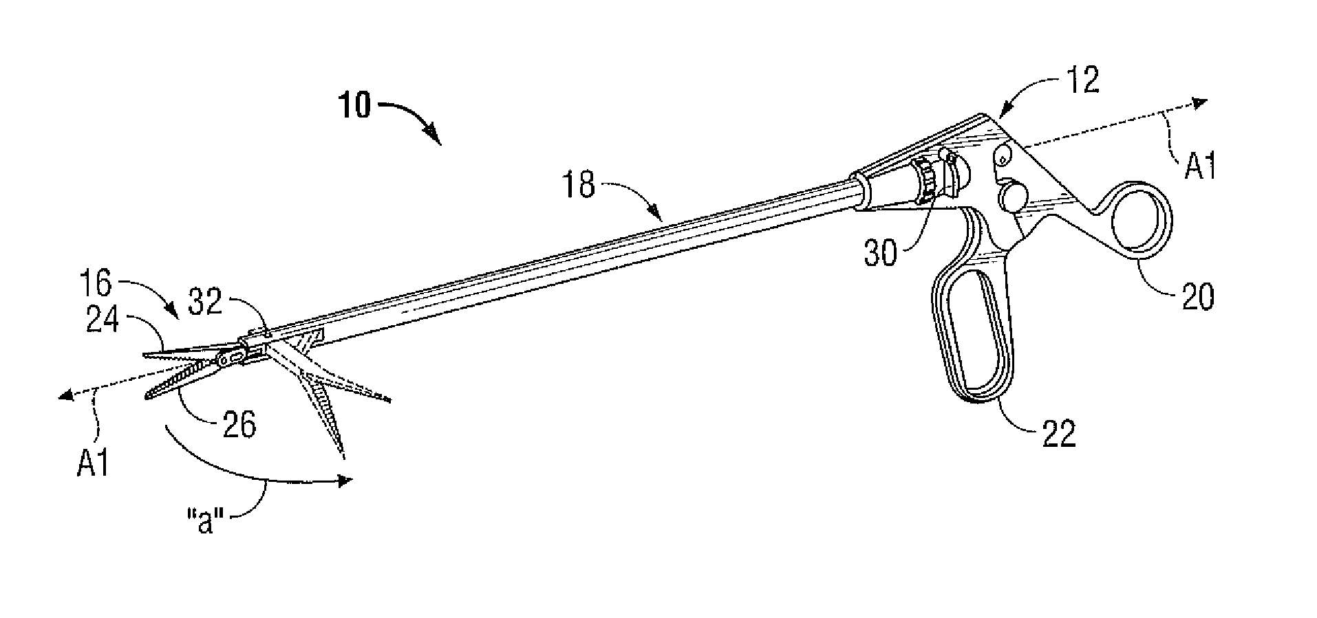
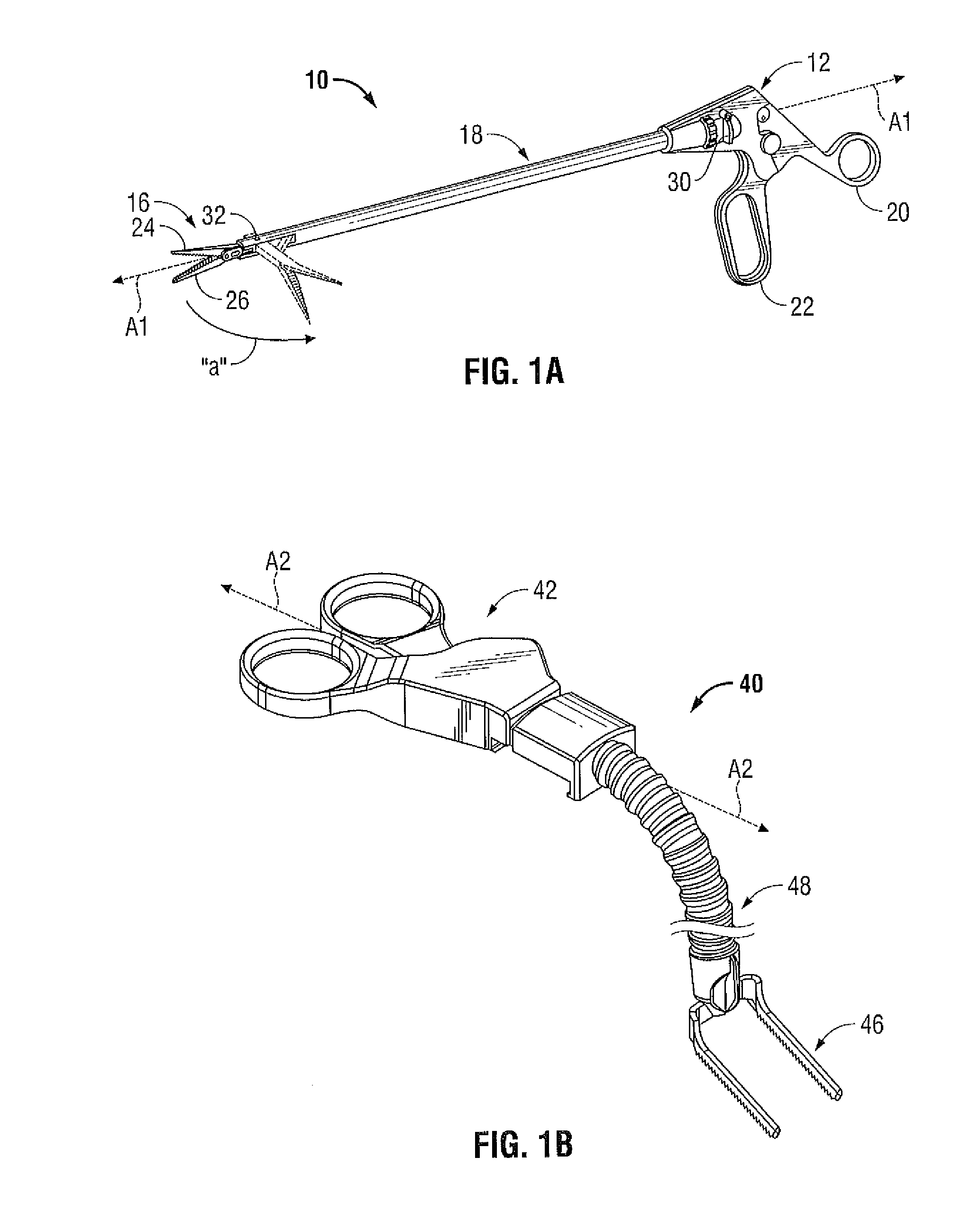
[0028]Referring initially to FIG. 1A, an articulating endoscopic instrument is depicted generally as 10. The instrument 10 includes a handle portion 12 near a proximal end, an end effector 16 near a distal end and an elongated shaft 18 therebetween. Elongated shaft 18 defines an instrument axis “A1” to which end effector 16 aligns for insertion through a cannula (not shown) or other suitable introducer. End effector 16 is articulatable off-axis (as indicated in phantom) to appropriately engage tissue. Handle portion 12 is manipulatable by the surgeon from outside a body cavity to control the movement of the end effector 16 positioned inside the body at a tissue site. For example, the surgeon may separate and approximate a pivoting handle 20 relative to a stationary handle 22 to respectively open and close jaw members 24, 26. Also, a surgeon may pivot lever 30 to cause the end effector 16 to articulate or pivot in a horizontal plane about a pivot pin 32. A more complete description o...


PUM


Abstract

An end effector for a surgical instrument includes a fixed bearing member with mounting surfaces for attachment to a distal end of the surgical instrument. At least one jaw member of the end effector is configured to move relative to an opposing jaw member between open and closed configurations, and a force transfer member is configured for longitudinal motion with respect to the fixed bearing member. The end effector also includes a reactive member that has a pivot boss about which the at least one jaw member rotates, and is coupled between the fixed bearing member and the at least one jaw member. The force transfer member applies a longitudinal force to the at least one jaw member at some lateral distance from the pivot boss to urge the at least one jaw member to move between the open and closed configurations.

Description

BACKGROUND[0001]1. Technical Field[0002]The present disclosure relates to an apparatus for remotely activating jaw members on an articulating surgical instrument. In particular, the apparatus provides an end effector capable of transferring a sufficient force to the jaw members to cause a therapeutic effect on tissue clamped between the jaw members.[0003]2. Background of Related Art[0004]Typically in a laparoscopic, an endoscopic, or other minimally invasive surgical procedure, a small incision or puncture is made in a patient's body. A cannula is then inserted into a body cavity through the incision, which provides a passageway for inserting various surgical devices such as scissors, dissectors, retractors, or similar instruments. To facilitate operability through the cannula, instruments adapted for laparoscopic surgery typically include a relatively narrow shaft supporting an end effector at its distal end and a handle at its proximal end. Arranging the shaft of such an instrumen...

Claims


Application Information

Patent Timeline
Patent Type & Authority Applications(United States)
IPC IPC(8): A61B17/29
CPCA61B17/29A61B2017/2937A61B2017/2936
Inventor CUNNINGHAM, JAMES S.
Owner TYCO HEALTHCARE GRP LP
Why Eureka
Try Eureka