Spindle Motor and Fabricating Method Thereof

Inactive Publication Date: 2008-07-17
HITACHI LG DATA STORAGE KOREA
View PDF9 Cites 22 Cited by
  • Summary
  • Abstract
  • Description
  • Claims
  • Application Information

AI Technical Summary

Benefits of technology

[0026]According to the present invention, since the shaft perpendicularity adjusting process need not be separately performed after the motor is completely assembled, it is possible to prevent the change of the shaft perpendicularity when the motor is used in products and also prevent the defective of the motor components that may be caused while adjusting the shaft perpendicularity.
[0027]Also, the present invention can obtain the accurate shaft perpendic

Problems solved by technology

Also, among the entire processes of manufacturing the spindle motor 10, the shaft perpendicularity adjusting process is complicate and its accuracy is difficult to obtain.
That is, the shaft perpendicularity adjusting process often causes defective spindle motors and decreases the productivity of the spindle motors.
However, when the core 26 is adhered to or press-fit into

Method used


Image

  • Spindle Motor and Fabricating Method Thereof
  • Spindle Motor and Fabricating Method Thereof
  • Spindle Motor and Fabricating Method Thereof

Examples


Embodiment Construction

[0036]Hereinafter, a spindle motor and a fabricating method thereof according to the present invent will now be described in detail with reference to the accompanying drawings.

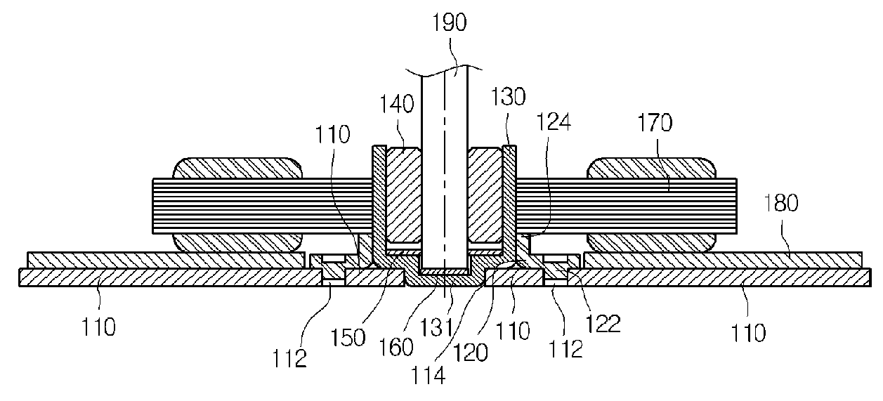
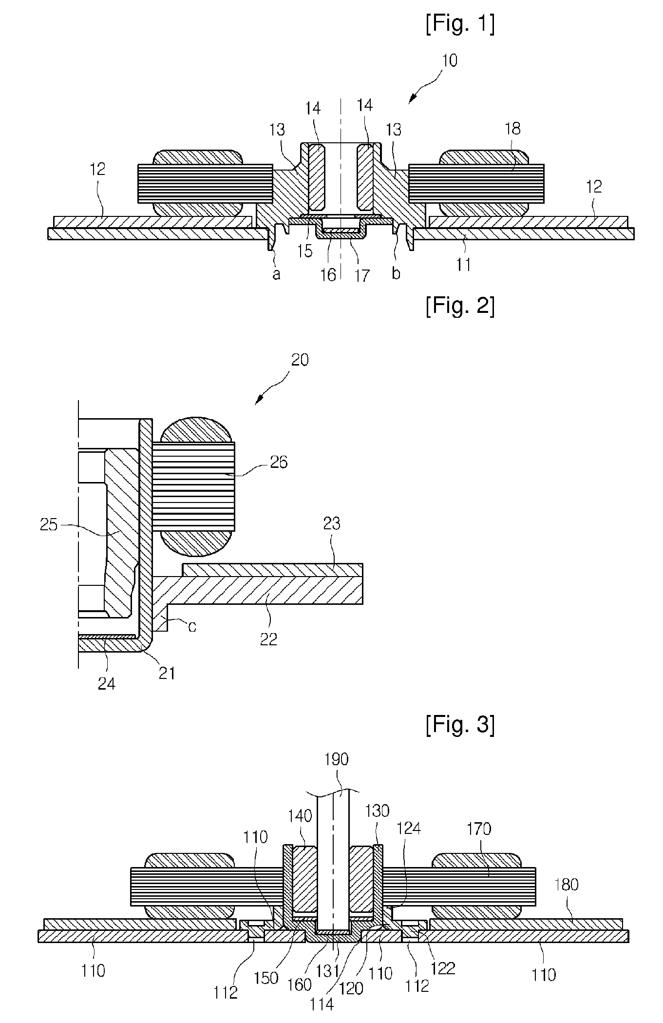
[0037]FIG. 3 is a sectional view of a spindle motor according to the present invention.

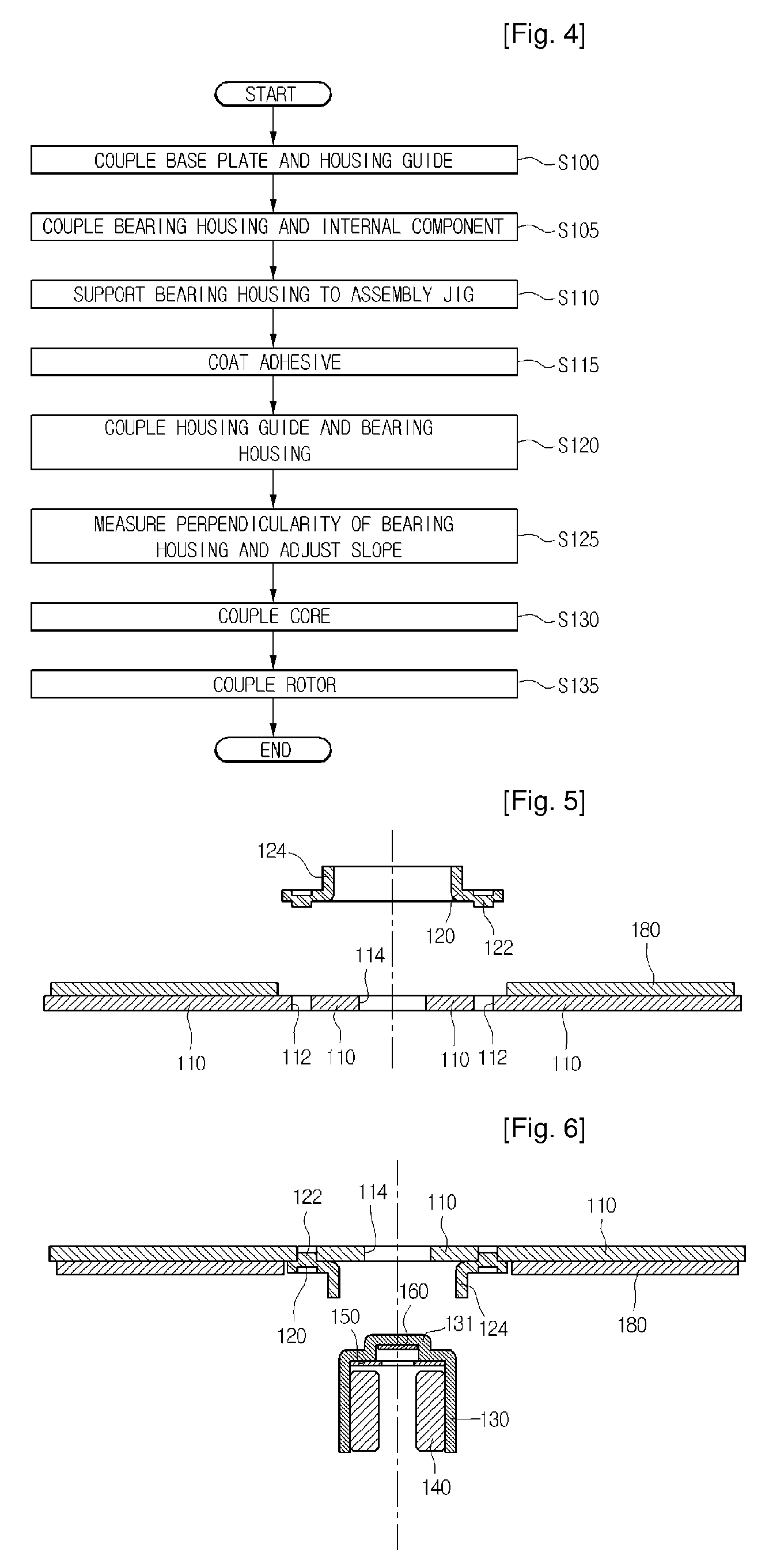
[0038]Referring to FIG. 3, the spindle motor includes a base plate 110, a PCB 180, a housing guide 120, a bearing housing 130, a bearing 140, a washer 150, a thrust plate 160, and a core 170. The spindle motor further includes a rotor 190 in an inside of the bearing 140. The rotor 190 is rotated by an electromagnetic force generated between the rotor 190 and a coil wound around the core as a stator.

[0039]The components of the spindle motor will be described below in detail.

[0040]The bearing housing 130 is provided in a cup shape by a deep drawing process. The bearing housing 130 has a downwardly convex portion 131 on a lower surface. The deep drawing process is a technique to press a sheet into a die using a punch. That is, ...


PUM


Abstract

A spindle motor, obtaining more accurate shaft perpendicularity and more convenient assembling process, is disclosed, the spindle motor includes: a rotor; a bearing housing into which the rotor is inserted; a base plate fixing the bearing housing; a housing guide fixed to the base plate, the housing guide having at least one vertical portion guiding an outer surface of the bearing housing; a printed circuit board mounted on the base plate; and a stator coupled to an outer surface of the bearing housing and supplied with power from the printed circuit board.

Description

TECHNICAL FIELD[0001]The present invention relates to a spindle motor, and more particularly, to a bearing housing for supporting a rotor and a base plate to which the bearing housing is fixed.BACKGROUND ART[0002]Spindle motors are widely used in electronic appliances (e.g., a projection television, a hometheater device, a drive for a computer, etc.) requiring precisely rotational devices. The spindle motors are small in size and can rotate at high speed. Also, the spindle motors are easy to precisely control and have low power consumption. Because of these advantages, the use of the spindle motors is expected to increase.[0003]Hereunder, a related art spindle motor will be described.[0004]FIG. 1 is a sectional view of a related art slim-type spindle motor.[0005]Referring to FIG. 1, the related art slim-type spindle motor 10 includes a base plate 11, a printed circuit board (PCB) 12, a bearing housing 13, a bearing 14, a core 18, a washer 15, a thrust plate 16, and a thrust stopper ...

Claims


Application Information

Patent Timeline
IPC IPC(8): H02K5/16H02K15/00H02K15/16
CPCH02K1/187H02K5/1675Y10T29/49012H02K15/14H02K2211/03H02K11/0068H02K11/30A61H33/10A61H33/065E03D11/13A61H2033/068A61H2201/025A61H2205/086A61H2205/087A61H2201/102A61H2201/50A61H2203/0431
Inventor LEE, TAE WOOK
Owner HITACHI LG DATA STORAGE KOREA
Why Eureka
Try Eureka