Chaotic signal transmitter using pulse shaping method

Inactive Publication Date: 2007-10-04
SAMSUNG ELECTRO MECHANICS CO LTD
View PDF6 Cites 72 Cited by
  • Summary
  • Abstract
  • Description
  • Claims
  • Application Information

AI Technical Summary

Benefits of technology

[0018]The present invention has been made to solve the foregoing problems of the prior art and therefore an aspect of the present invention is to provide a chaotic signal transmitter which does not

Problems solved by technology

But such a typical modulation method requires complex technical interpretation for the original signal during demodulation.
However, as shown in the graph of FIG. 2, in the conventional ultra-wide band transmitter, almost no change is exhibited in the slope C1 from the lowest point A1 to the highest point B1, which makes it difficult to determine the highest point B1.
T

Method used


Image

  • Chaotic signal transmitter using pulse shaping method
  • Chaotic signal transmitter using pulse shaping method
  • Chaotic signal transmitter using pulse shaping method

Examples


Example

[0030]Exemplary embodiments of the present invention will now be described in detail with reference to the accompanying drawings.

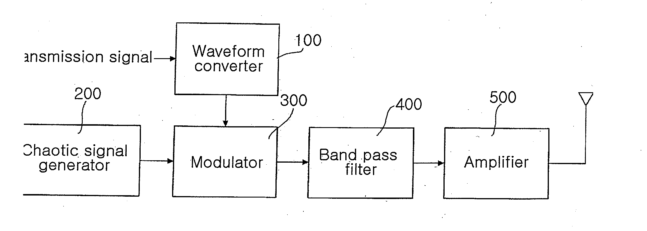
[0031]FIG. 3 is a block diagram illustrating a chaotic signal transmitter according to the present invention.

[0032]Referring to FIG. 3, the chaotic signal transmitter according to the present invention includes a waveform converter 100 for converting the waveform of a transmission signal, a chaotic signal generator 200 for generating a chaotic signal and a modulator 300 for modulating the chaotic signal from the chaotic signal generator 200 according to the transmission signal from the waveform converter 100.

[0033]First, there is transmission data a user desires to transmit. The transmission data is made up of ‘0’ and ‘1’. The transmission data is transformed into a transmission signal. Preferably, the transmission signal may be a square wave pulse.

[0034]The waveform converter 100 converts the waveform of the transmission signal. That is, the waveform conv...


PUM


Abstract

The invention relates to a chaotic signal transmitter using a pulse shaping method to amplitude-modulate a chaotic signal according to a transmission signal, thereby transmitting the chaotic signal having various slopes. The chaotic signal transmitter includes a waveform converter for blocking high frequency component of the transmission signal to convert the waveform of the transmission signal and a chaotic signal generator for generating the chaotic signal. The chaotic signal transmitter further includes a modulator for amplitude-modulating the chaotic signal according to the waveform-converted transmission signal.

Description

CLAIM OF PRIORITY[0001]This application claims the benefit of Korean Patent Application No. 2006-0028085 filed on Mar. 28, 2006, in the Korean Intellectual Property Office, the disclosure of which is incorporated herein by reference.BACKGROUND OF THE INVENTION[0002]1. Field of the Invention[0003]The present invention relates to a chaotic signal transmitter and, more particularly, to a chaotic signal transmitter using a pulse shaping method to amplitude-modulate a chaotic signal according to a waveform-converted transmission signal, thereby transmitting a chaotic signal having various slopes.[0004]2. Description of the Related Art[0005]In general, a chaotic signal is characterized as an a periodic signal with no particular phase, and a wide band signal. A typical periodic signal has a regular phase in accordance with time and thus may be distorted or cancelled when an interference signal of an antiphase is added. However, a chaotic signal has no clear phase so that it does not interf...

Claims


Application Information

Patent Timeline
IPC IPC(8): H04L9/00H04J13/00H04B1/69
CPCH04L27/001H04L25/03834H04B1/04H04L25/00H04L27/02
Inventor PARK, SANG GYUPARK, HYUNG CHULYANG, CHANG SOO
Owner SAMSUNG ELECTRO MECHANICS CO LTD
Why Eureka
Try Eureka